Determining the factor of safety under the asymmetrical stress cycle
For designs under the asymmetrical stress cycle the simpled diagram CML of the limit specimen stress is accepted (see Fig. 11.6 and 11.15). Taking into account the stress concentration, the influence of the absolute detail cross section dimensions, the surface condition we can draw the diagram of the limit detail stresses. There by according to the given experiences the enumerated factors influence is dated to only the variable composing cycle i.e. the amplitude  The limit stress amplitude for the specimen according to the formula (11.15) is
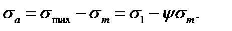 (11.18)
The limit stress amplitude for the detail according to the stated above is equal to
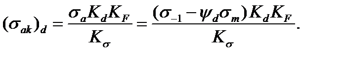 (11.19)
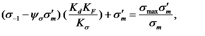
The line equation of the limit stresses EN (Fig. 11.15) to the detail we get the form
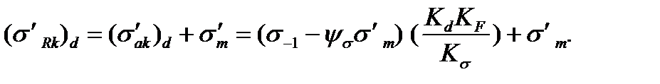 (11.20)
Here the current coordinates are denoted by strokes.
Now calculate the details factor of safety under the variable stress action  and
and  (the point R of the diagram, Fig. 11.15).
| Development type |
| Detail |
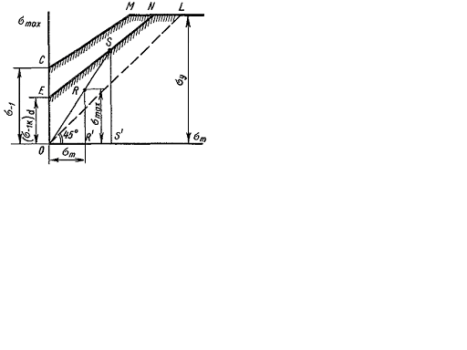
Fig. 11.15.
Suppose that under the detail load increase we have the relation  This loading is called simple.
In this case the limit point according to the rupture is point S.
The safety factor is equal to the relation of the segments SS’ and RR’:
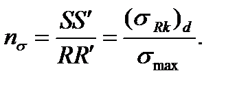 (11.21)
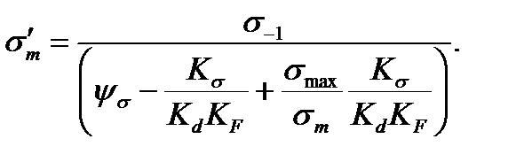
We will find the value  (the point ordinate S) as the result of combined solving the line equations of the line EN and the line OS. The line equation has the form:
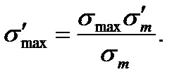 (11.22)
(The current coordinates are denoted by the strokes).
Equating the right formula parts (11.20) and (11.22) we get
 (11.23)
from which
 (11.24)
Substituting the value  to the formula (11.20) or (11.22) we find the point coordinate S.
We will find the value  (the point ordinate S) as the result of combined solving the line equation of the line EN and the line OS. The line equation OS has the form:
 (11.25)
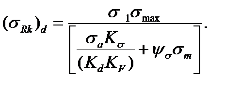
Consequently, the following finished relation for determining the safety factor is based on the formulas (11.21):
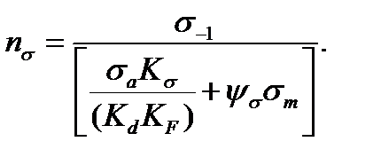 (11.26)
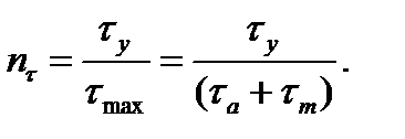
Analogically we have in torsion:
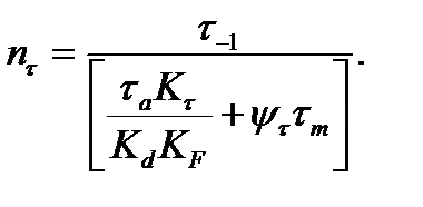 (11.27)
Under the combined stress condition, for example, in torsion with bending the safety factor is calculated by the formula
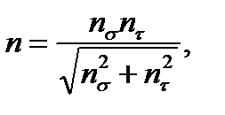 (11.28)
and the values  and
and  are calculated by the formulas (11.26) and (11.29).
Except the safety factor of the fatigue strength it is necessary to find the safety factor of the plastic deformations strength as the point s can occur above the line ML. The safety factor of the plastic deformations strength is calculated by the formula
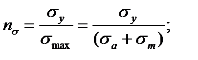 (11.29)
 (11.30)
The design safety (real) factor is less of the factors calculated by the formula (11.26) or (11.29) or in torsion accordingly to the formula (11.27) or (11.30). In the case of the design under bending with torsion in the formula to determine the general safety factor the lesser of the values  and
and  calculated as pointed above must be substituted.
Дата добавления: 2020-10-25; просмотров: 864;
Поиск по сайту
Узнать еще
- A lot of machine details in their function time are repeatedly subjected to variable loads stresses in time.
- As we can see the shearing strain and shearing stress in torsion are directly proportional to the distance from the centroid of the section.
- Calculating stresses under the uniformly accelerated motion
- Control for cultivation. Antimicrobial factors.
- Determination of stresses at the inclined sections in tension (compression) in two directions
- Determining displacements and stresses under the impact
- Determining the internal forces by the method of sections. Stresses

Публикации по технике и механике
Публикации по биологии

Публикации по информатике

Публикации по строительству
Публикации по физике

Публикации по химии

Публикации по электронике

Публикации по искусству
Публикации по географии
Публикации по медицине