Laboratory work № 3
«Fatigue test under pure bending»
Introduction
While in operation a lot of machine parts and construction elements are subjected to loads action, changeable in time. If the stresses level is over a certain one, the material stores rupture, that lead to cracks appearance and final breakage.
This disruption happens at stresses much lower than at static action.
The process of storing ruptures in the material, under fluctuating stresses that lead to cracks appearance and final breakage is called the fatigue of a material. The material property to resist to this fatigue is called the fatigue resistance.
Low-cycle and multiple-cycle fatigue are distinguished.
The multiple-cycle fatigue is the fatigue of a material, when macrocracks or full breakage happen at 5·104 cycles and more.
The low-cycle fatigue is the fatigue of a material, when macrocracks or full breakage happen in the elastoplastic area before 5·104 cycles.
The division into low-cycle and multiple-cycle fatigue is conditional.
To calculate the fatigue limit it is necessary to have a number of ultimate limit states properties. One of them is the fatigue limit or the endurance range.
The endurance range is the maximum stress at which the specimen doesn’t break before the test base.
For steel specimen in usual conditions the test base is 107 cycles, for non-iron metals and high-resistance steels the test base is 108 cycles.
The endurance range is determined by experiment.
The sequence of specimen loading is set so as to produce the stress state analogous to the working conditions of a part.
The main types of loading are:
a) pure bending at rotation;
b) the same in one plane;
c) cross-buckle at console round specimen rotation;
d) the same in one plane of round and not round specimen;
e) cross-buckle of console round and not round specimen.
Tests are also performed at combination of loading types.
Theory
The plastic deformation localization near the rupture crack is the distinctive feature of the fatigue fracture even in cases when a detail or a specimen has been manufactured from a material that the large plastic deformation precedes the analogous static load condition of the rupture. For example, the rupture of the tension cylindrical specimen made of a soft steel, advances the plastic deformation in all the work part, approaching 20-30%. While under the longitudinal sign variable loading of a similar specimen, the fatigue fracture occurs without the essential plastic deformation. And it can be determined by the surface crack character and the material structure, that the plastic deformation has taken place in some small regions.
The external breaking consists of two ranges: the range of the gradual crack development and the final rupture range.
The gradual crack development has a dull smooth surface, because under the frequent repeating loading the crack ends approach and fall apart, so the crack becomes smooth. The final rupture range has a crystal form due to the cleavage-type rupture.
The materials fatigue strength depends on not only the state stress form but the stress change character in time.
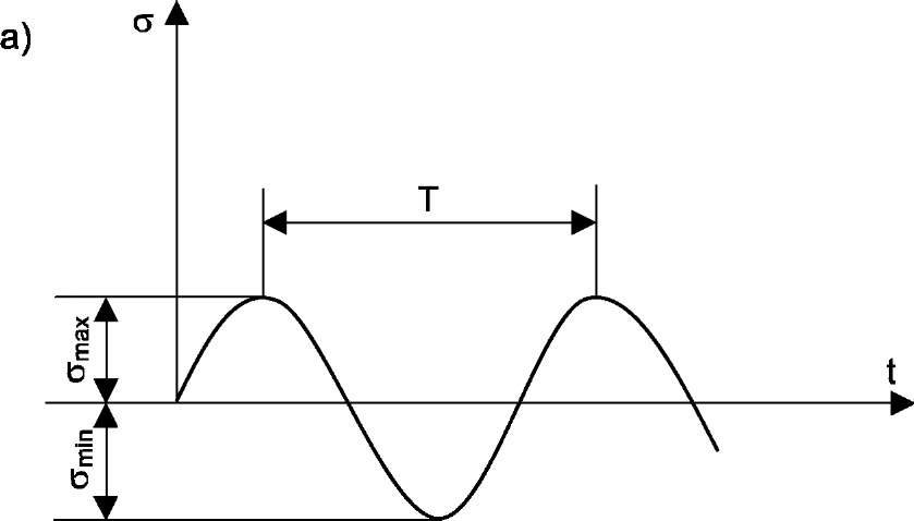
The stress cycle is called their one-time change corresponding to the full period T changes.
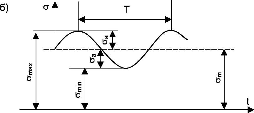
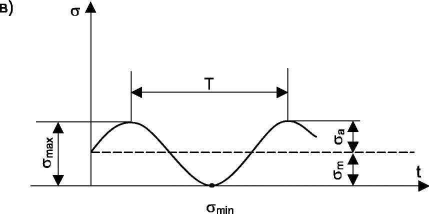
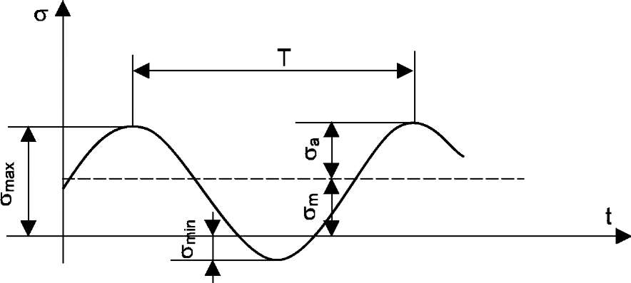
The stress change character can be different in time. The simplest sine changes are shown in Fig.1.
|
|
|
| с) |
|
| d) |
|
Fig. 1. The stresses change during time
a) - the symmetrical cycle, b) - the constant sign,
c) - the pulse cycle, d) - the variable sign
Let us consider the basic cycle characteristics. The minimum cycle stress relation  to the maximum one is called the coefficient of the cycle asymmetry:
For the symmetrical cycle (fig. 1a) we have  , and the coefficient of cycle asymmetry r = -1. Two parameters characterize any stress cycle:
 ,
, 
where  is the average constant cycle stress,
  is the cycle amplitude. The difference
  is called the stress scope.
The process of the crack formation under variable stresses is connected with the plastic deformation accumulation. It follows, that the fatigue rupture is determinated only by the stresses and  . Besides, as it is shown by experiments, the stress change frequency influence is immaterial. The high temperature tests are the exceptions as well as those under the corrosion medium action. As a result we have to know only the values and or and to evaluate the fatigue rupture for the given cycle conditions.
The tests for the symmetrical cycle are the most widespread. In this case the received fatigue strength value is noted by  .
.
The first machine for the fatigue tests was built by A. Wohler in the middle of the XlX-th century.
To get the fatigue resistance characteristics we need to conduct more than ten tests of the similar specimens. Each specimen is tested up to the rupture (or up to the cycle base number) only for one stress amplitude. The test process is rather long.
Approximately about half the specimens are tested under the stresses having 0,7 - 0,5 level of the ultimate strength  .
.
The tests are conducted in the following sequence. The 0,7  stress is set for the first specimen, then it is loaded up to the rupture and fixed the N cycle number, which the specimen has endured. The process is repeated for the next specimen under the gradual increase of the maximum stress level .
Wohlers curve is drawn for each specimen using the test data ( and N). The curve is drawn in the half-logarithm coordinate system:  is put on the ordinate axis and log N is put on the abscess axis.
The fatigue curve appears as in Fig.2. for low-carbon steel.
|
Fig. 2. The fatigue curve
Wohlers curve approaches asymptotically to the maximum stress value of the cycle under which the specimen does not break up to the test base. This stress is the  fatigue strength.
Installation
To conduct tests a bend-torsion machine for a pure bending of round specimens is used (Fig.3).
| Fig.3. The bend-torsion machine to test the pure bending of the round specimens under torsion |
Specimen 1 is held in the torsion grips 2 and 3. The load creates the effort by hanging on shackles 4 and 5. Counter 6 fixes the cycle N number. Electric motor 7 is disconnected automatically by contact 8 when the specimen is broken. The bending moment diagram is shown in Fig.3.
The maximum normal stress is determined by the formula
where d is the specimen diameter of the work part,
W is the section modulus of the specimen cross-section,
M is the bending moment, F is the load.
The test specimen is manufactured under GOST 25.502-79 (fig. 4).
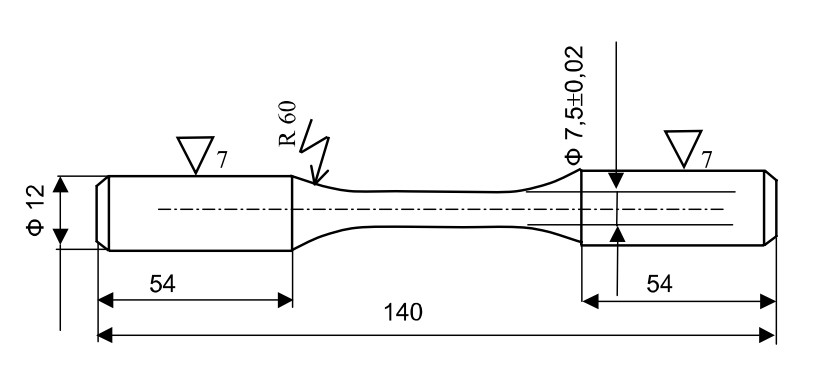
Fig.5. The specimen for test
СПИСОК ИСПОЛЬЗОВАННОЙ ЛИТЕРАТУРЫ
1. New Webster’s dictionary of English language College edition. Prepared by the publisher’s editorial staff under the general supervision of Dana F. Kelierman. – Delhi – 110007 India, 1989. – 1824p.
2. Англо-русский политехнический словарь. Под редакцией А. Г. Чернухина. – М.: Советская энциклопедия, 1971. – 672 с.
3. Орловская И.В., Самсонова Л.С., Скубриева А. И. Учебник английского языка для студентов технических университетов и вузов. - 2-е изд. перераб. и доп. – М.: Изд-во МГТУ им Н.Э. Баумана, 2000. – 390 с.
4. Сборник терминов по классической механике. На 5 языках. – WYDAWNICTWA NAUKOWO-TECHNICZNE: WARSZAWA. - 1965. – 192 c.
4. Сиполс О.В., Широкова Г.А. Англо-русский учебный словарь с синонимами и антонимами. Общенаучная лексика. – М.: Флинта: Наука, 2003. – 608 с.
5. Лексический минимум по механике (на базе английского языка). Под редакцией М.М. Глушко – М.: Изд. МГУ. 1979. – 136 c.
6. Шляфер Ю.Л. Англо-русский краткий научно-технический словарь. – М.: Инфра-М., 1994. – 109 с.
Дата добавления: 2020-10-25; просмотров: 691;
Поиск по сайту

Публикации по технике и механике
Публикации по биологии

Публикации по информатике

Публикации по строительству
Публикации по физике

Публикации по химии

Публикации по электронике

Публикации по искусству
Публикации по географии
Публикации по медицине