As we can see the shearing strain and shearing stress in torsion are directly proportional to the distance from the centroid of the section.
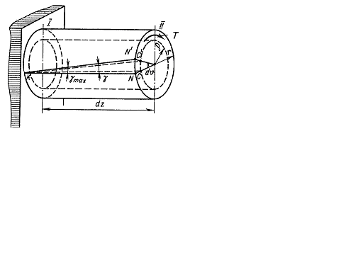
Fig. 4.6.
The shearing stress diagram over the bar cross section is shown as in Fig. 4.5 to the right.
The shearing stresses are equal to zero at the centroid of the round section. The maximum shear stresses will be at the section points located on the bar surface.
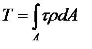
Knowing the distribution law of the shearing stresses we can easily determine them, the twisting moment at the section being the resultant moment of the shearing stresses at the section:
 , (4.4)
where  is the elemental twisting moment of the internal forces acting on the element of area dA.
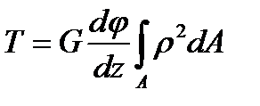
Substituting the stresses value from the formula (4.3) in (4.4) we get
 (4.5)
(4.5)
Bearing in mind that
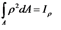 , (4.6)
where  is the polar moment of inertia of the section, we receive
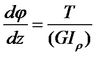 (4.7)
(4.7)
Substituting the value  in the formula (4.3) we have
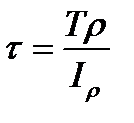 (4.8)
(4.8)
In this way the final formula for determining the shear stresses is
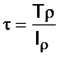 (4.9)
(4.9)
As it can be seen from this formula the stresses  are the same at the points removed equally from the section center.
The maximum stresses are at the points of the section contour:
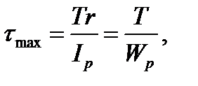 (4.10)
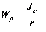 . (4.11)
We call the sectional modulus of torsion or modulus of twist the geometrical characteristics Wp.
The statically strength condition of the shaft is
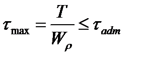 , (4.12)
here  is the allowable working shear stress.
Besides the strength check by this formula we can find the shaft diameter or determine the allowable twisting moment when the other value is known.
Keeping in mind that for the round solid section Wp = 0,2d3 we get
 (4.13)
The allowable twisting moment from the strength condition is determined by the formula
 (4.14)
Дата добавления: 2020-10-25; просмотров: 743;

