Determining the stresses in the round section bar
The twisting moments mentioned above are but the internal resultant forces. In fact, the distributed internal shearing stresses are set up at the cross section of the twisting bar whose determining will be further considered.
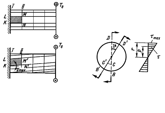
Fig. 4.5.
First of all let us get acquainted with the experiment results. If the rectangular line network is drawn on the bar surface of the round section, after deforming then we shall have (Fig. 4.4):
1) the rectangular line network tranfers into a network consisting of the parallelograms. The fact testifies the shearing stresses at the bar cross sections and according to the law of the twin shear stresses also at the longitudinal sections;
2) the distances between the circumferences, for example I and II, do not change. The bar length and its diameter do not change either. Naturally, one can assume that each cross section is rotated in its plane at some angle as the rigid whole. It can be considered that the radius of all cross sections will be rotated at different angles being rectilinear.
On this basis it can be accepted that the shearing stresses there set up at the bar cross section in torsion.
To derive the distribution law of the shearing stresses over the cross section of the twisting bar let us consider in more details the bar deformations (Fig. 4.4 and Fig. 4.6). The bar portion between I and II sections is represented in Fig. 4.6 in a larger scale. Fig. 4.4 shows one side KN of the element KLMN.
The angle of the KLMN element slide on the bar surface equals the relation of the length NN` to the element length dz (Fig. 4.6):
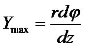 . (4.1)
Removing mentally from the considered bar portion the cylinder of the arbitrary radius r and repeating the same reasoning we get the angle of the slide for the element at a distance r from the bar axis:
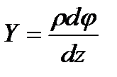 . (4.2)
On the basis of Hooke¢s law we have
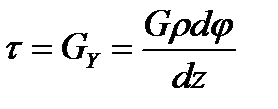 . (4.3)
Дата добавления: 2020-10-25; просмотров: 624;

