The bars being in torsion and rotation are called the shafts.
We shall use mainly the plane representation except axonometric as a simpler one. We shall represent torques and twisting moments in the form of the line with two circles. Put the point in one of them defining the arrow origin (directed to us) and the other one - the cross directed from us (Fig. 4.2).
To determine the twisting moments T arising at the shaft sections under the action of the torques or the transverse load we shall apply the method of section. Let us mentally make the section of the bar (Fig. 4.2), for example a - a, then remove one part of it, in this case the left one and consider the equilibrium of the remaining portion. The interaction of the bar portion is replaced by the twisting moment T balancing the torque  . For equilibrium of the cut portion there must be the sum of all moments acting on it equal to zero. Hence for the case considered
If some torques act on the cut portion, we can be convinced of the reasoning in analogy that the twisting moment for any section is defined to be the algebraic sum of the moment of the applied couples that lie to one side of the section in question.
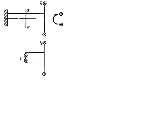
Fig. 4.2.
To represent vividly the distribution character and the values of the twisting moments along the length of the bar there are drawn the diagrams of the moments. Their plots are analogous to the diagrams of the normal force under tension or compression. It is necessary to agree upon the sign rules to draw the diagrams. There is no universally recognized sign rule of the twisting moment. Any sign rule can be accepted. The accepted rule must be kept for all diagrams.
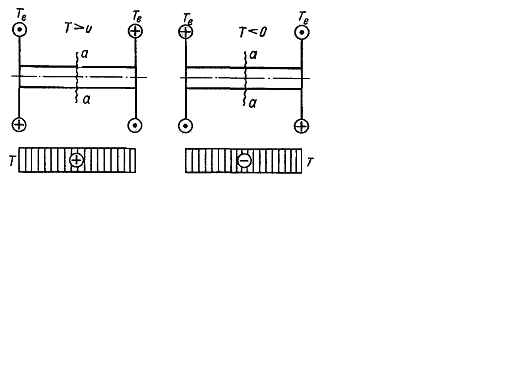
Fig. 4.3.
Let us accept the following sign rule (Fig. 4.3). The twisting moment for the section a – a is considered positive when the torque rotates the cut portion anti – clockwise looking at the section of the cut portion. If the torque rotates the cut portion clockwise (lookig at the section), the twisting moment is considered negative. We shall explain the drawing of the twisting moment diagram by the following example (Fig.4.4). Let us consider the shaft CD supported by the bearings B and A and being in the equilibrium under the action applied to the moment in the sections E, K and L.
Let us do the section a – a on the portion between D and L and considering a free – body diagram of the right shaft in equilibrium, we get convinced that T=0. If we do the section b – b in any part of the region LK, we get T=20 kNm from the equilibrium of a free – body diagram of the right shaft.
The moment is considered positive in agreement with the accepted sign rule. When by making the section c – c in the region KE, we get 20 – 30 – T=0 from the equilibrium of a free – body diagram of the right shaft, hence T= -10 kNm.
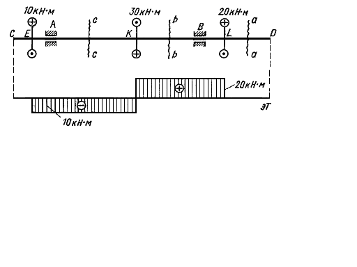
Fig. 4.4.
Fig. 4.4.
This diagram has the shape of two rectangles. It must be noted that the diagram ordinates have an abrupt jump of the torque value at the point where the couple is applied.
Дата добавления: 2020-10-25; просмотров: 744;
Поиск по сайту
Узнать еще

Публикации по технике и механике
Публикации по биологии

Публикации по информатике

Публикации по строительству
Публикации по физике

Публикации по химии

Публикации по электронике

Публикации по искусству
Публикации по географии
Публикации по медицине