Example of the shaft calculation in bending with torsion
In designing the shafts subject to combined torsion and bending they are calculated on the static strength according to the maximum momentary stresses and also on the fatigue under the protracted acting variable stresses.
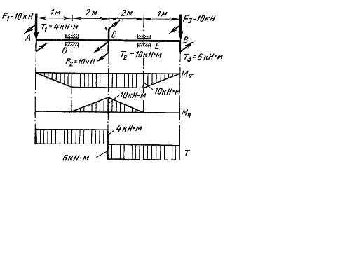
Fig. 7.7.
Let us give an example of the shaft calculation (Fig. 7.7 a) on the static strength. The shaft is subject to the action of two vertical forces F1 and F3,a horizontal force F2 and three external moments: 

 causing the torsion deformation. The shaft material is steel 45 with the yield point of
  and the ultimate strength of
Present the general factor of safety n as the product of three particular coefficients:
n=n1n2n3
Accept n1=1,3 (taking into consideration the average precision of determining the stresses), n2=1,4, n3=1,3 (taking into consideration the average degree of the detail responsibility). Thus, the general factor of safety is
n1=1,3×1,4×1,3=2,36
The allowable working stress is 
1. Draw the bending moment diagram Mu from the vertical forces (Fig. 7.7 b).
2. Draw the bending moment diagram from the horizontal forces. The diagram Mx is conditionally superposed with the drawing plane and it is shown in Fig. 7.7 c. Since the shaft section is circular, the calculation is fulfilled by the formulas of the plane bending and the resulting (total) moment.
3. The total bending moment at the section C and E:


4. Draw the twisting moment diagram. Diagram T is shown in Fig. 7.7 d.
Determine the shaft diameter in the danger section C where the maximum bending moment  acts as well as the twisting moment
Apply the fourth strength hypothesis for the section selection:

from which

Дата добавления: 2020-10-25; просмотров: 683;

