Calculation of the thin-walled vessels
In technics there often occur the vessels whose walls are subject to pressure from liquids, gases and loose bodies (steam boilers, reservoirs, working chamber of motors, cisterns and the like). If the vessels have a shape of revolution bodies and their wall thickness is insignificant while the load is axisymmetric, the determining of stresses arising in their walls under the load is done very simply.
In such cases, – it is not much of an error, it can be accepted that only normal stresses arise in the walls and that stresses are distributed over the wall thickness.
The calculations based on such assumptions are well verified by the experiments if the wall thickness does not surpass approximately  the minimum radius of the wall curvature.
Remove from the vessel wall an element with the dimensions of  and
and  . Denote the wall thickness by t (Fig. 8.1). The radius of the curvature in this place is
  and
and  .The internal pressure
  normal to the element surface is the load on the element.

Рис. 8.1.
Replace the interaction between the element and the remaining portion of the vessel by the internal forces having intensity  and
and  . As the wall thickness is insignificant, as it has been noted, these stresses can be considered as uniformly distributed over the wall thickness.
Compose the element equilibrium condition by projecting the forces acting on the element in the direction of the normal nn to the element surface. The load projection is equal to  . The stress projection
  on the normal direction presents the segment ab which is equal to
  The stress projection acting on the border 1-4 (and 2-3) is equal to
  . Analogously, the stress projection acting on the border 1-2 (and 4-3) is equal to
  .
.
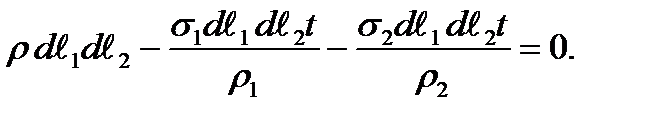
Having projected all forces applied to the removed element on the normal direction nn we get
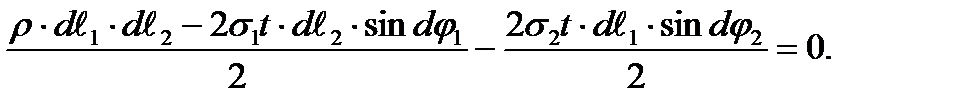
On account of a small element dimension this can be accepted.
Considering this from the equilibrium equation we get

Taking into account that  and
and 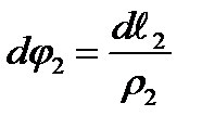 we have
Reducing by  and dividing by t we get
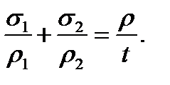 (8.1)
(8.1)
This formula is called Laplas’s formula. Consider the calculation of two vessel types often occurring in practice: spherical and cylindrical. Limit ourselves to the cases of the internal gas pressure action.
| а) b) |
Fig. 8.2.
1. The spherical vessel. In this case we have  and
and  From (8.1) it follows that
 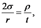 from which
 (8.2)
(8.2)
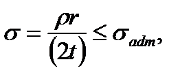
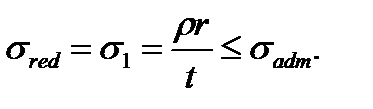
As in the given case the plane stress takes place, for the stress analysis it is necessary to apply this or that strength theory. The principal stresses have the following values: 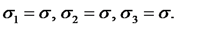 Under the third strength theory:
 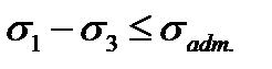 Substituting
  and
and  we get
 (8.3)
(8.3)
i.e. checking the strength is realized as in the case of the uniaxial stress.
According to the fourth strength hypothesis  . As in the given case
  , we have
 (8.4)
(8.4)
i.e. the same condition and according to the third strength hypothesis.
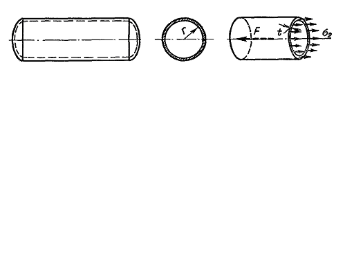
2. The cylindrical vessel. In this case  (the cylinder radius) and
  (the curvature radius of the forming line of the cylinder).
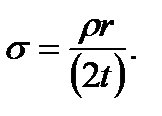
From Laplas’s equation we get  from which
 (8.5)
(8.5)
To determine the stress  we cut the vessel by the plane perpendicular to its axis and consider the equilibrium condition of one of the vessel parts (Fig. 8.2 b).
Projecting all forces on the vessel axis acting on the part cut we get
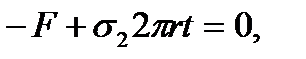 (8.6)
(8.6)
where 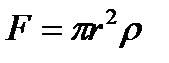 - the pressure force resultant of the gas on the vessel bottom.
Thus 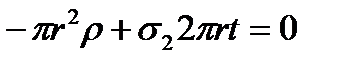 from which
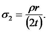 (8.7)
(8.7)
Note that the ring area is calculated as the product of the circle length and the wall thickness because it is thin-walled and being the cylinder section over which there act the stresses  . Comparing
  and
and  in the cylindrical vessel we see that
The strength condition according to the third strength hypothesis for the cylindrical vessel is
 (8.8)
(8.8)
The strength condition according to the fourth strength hypothesis is
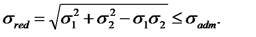 (8.9)
(8.9)
Example. Determine the wall thickness of the cylindrical vessel for saving the liquid with the specific weight g=10 kН/m3, the vessel dimentions shown in Fig. 8.3. The allowable working stress for the wall material is  = 100 МPа =100.103 kPа.
Solving. The liquid pressure on the wall vessel is proportional to the distance from the free surface:
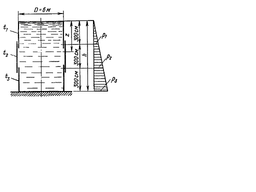
Fig. 8.3.
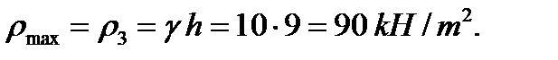
If the wall thickness is constant the calculation then is made with the maximum pressure on the foundation:
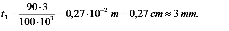
The wall thickness is determined by the formula:
Дата добавления: 2020-10-25; просмотров: 708;
Поиск по сайту
Узнать еще

Публикации по технике и механике
Публикации по биологии

Публикации по информатике

Публикации по строительству
Публикации по физике

Публикации по химии

Публикации по электронике

Публикации по искусству
Публикации по географии
Публикации по медицине