Bending in two planes (non-uniplanar bending)
The non-uniplaner bending arises when the internal forces perpendicular to the bar axis do not lie on the plane passing through the principal axis of its cross section (Fig. 7.1). In this case the bending moment arising at the cross section can be decomposed into two bending moments acting on the planes passing through the principal axes of the section. Thus, the non-uniplanar bending can be considered as the combination of two plane bends on the mutually perpendicular planes.
Under the non-uniplanar bending the normal stresses at any point of the cross section will be equal to the algebraic sum of stresses from bending into both planes.
Let us consider, for example, the point C of the support section having the x and y-conditions about the principal axes.
At the section we have:
a) the bending moment arising under the bar bending in the vertical plane with the neutral x-axis
 (7.1)
(7.1)
b) the bending moment arising under the bar bending in horizontal plane with the neutral y-axis
 (7.2)
(7.2)
Here Fu and Fh are the vertical and horizontal components of the force F;  is the beam length;
  is the angle of the force plane inclination with respect to x-axis.
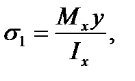
The tension stresses arise in the upper half beam (including at the point) under bending in the vertical plane and in the lower half beam compressions arise because the convex bar side will be on the top. The stress at the point C is determined by the following formula already known from the plane bend theory:
 (7.3)
(7.3)
Where y is the distance from the neutral x-axis to the point C; Ix is the second moment of the beam cross section x-axis.
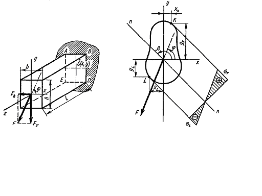
Fig. 7.1. Fig. 7.2.
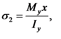
Because of bending in the horizontal plane the tension stresses arise in the right half beam and consequently at the point C and tension ones arise in the left half beam because the convex bar side under bending in the horizontal plane will be to the right. To be convinced of it bend a flexible ruler in the horizontal plane. The stresses at the point C will be determined by an analogous formula
 (7.4)
(7.4)
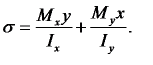
where x is the distance from the y-axis the neutral axis under bending in the horizontal plane to the point C; Ix is the second moment of the bar cross section about y-axis. The sum stress at the point C is
 (7.5)
(7.5)
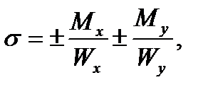
This formula is also valid for any bar section shape. If the section has the salient angle points for which Xmax and Ymax are achieved simultaneously (a rectangle, a double - T profile), the maximum stresses arise at these points:
 (7.6)
(7.6)
where 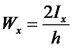 is the section modulus about the x-axis;
 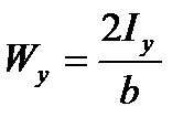 is the section modulus about the y-axis.
It is evident that the section angle points are dangerous where the stresses with the same sign are added.
For the case represented in Fig. 7.1 such section points will be the points B and E, in this casethe point B is in the tension region and the point E is in compression one.
That is why the stresses at the points B and E are equal:
 (7.7)
(7.7)
For the section of an arbitrary shape not having jutting angle points it is previously necessary to find the «dangerous» points, i.e. those section points where the maximum tension and compression stresses will act (Fig. 7.2).
At first the position of the zero line in the non-uniplanor bending is determined i.e. the geometric place of the section points at which the normal stresses are equal. In other words the line dividing the section part into tension and compression one is determined. Let it be the line nn.
Under bending the stresses increase according to the distance from the zero line.
It can be seen that the equation (7.5) represents itself the plane equation passing through the zero line. The ordinate measured along the normal from the cross section to this plane is equal numerically to the stress at the given point. It will be maximum for that point which is farther than the rest all from the zero line.
Taking it into consideration we conclude that the points to be verified concerning the stresses will be the ones most remote from the zero line, i.e. the points K and Z. For the material working equally in tension and compression the point with the largest stress arisen is dangerous.
We get the equation of the zero line by making equal the left part of the formula (7.5) to zero:
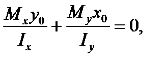 (7.8)
(7.8)
or
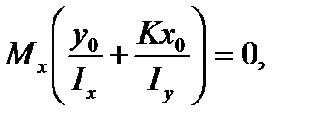 (7.9)
(7.9)
where in accordance with the formulas (7.8) and (7.9) we have
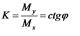 (7.10)
and x0and y0are the running coordinates of the zero line points. As Mx=0 then
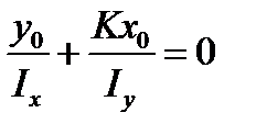 (7.11)
Дата добавления: 2020-10-25; просмотров: 814;

