The tension diagram of the lowcarbon steel
The mechanical characteristics of the materials i.e. the values characterizing their strength, ductility, elasticity and the elastic constant Е and  which are necessary for a designer to choose the material and calculate the details, can be received by mechanical testing the standard specimens from the material tested.
Let us consider the diagram received under the statical tension of the low-carbon steel (for example steel Ст.3, Fig.2.2) that is the most widespread and important mechanical testing.

Fig. 2.2.
A special unit of the testing machine draws the diagram automatically, the diagram expresing the relation between the tension force and the total elongation in the F and  coordinates. To study the material mechanical properties independent of the specimen’s sizes a diagram in the coordinates “stress-relative elongation” is used. These diagrams differ only on scales.
The low-carbon steel tension diagram is presented in Fig.2.3. The diagram has the following distinctive points:
The A point corresponds to the proportional limit.
The maximum stress up to which the deformations increase as proportional to the load i.e. when Hoke’s law is correct, - is called the proportional limit  (for the steel G.3
  =200 MPa).
Point A also practically corresponds to another limit which is called the elastic limit.
The maximum stress before the deformations remain practically elastic is called the elastic limit  .
.
The C point corresponds to the yield point.
The stress at which a visible elongation in the specimen with no loading increase appears is called the yield point  (as for steel Ст.3
  = 240 MPa).
The yield point is the basic mechanical characteristics while evaluating the strength of the plastic materials.
The B point corresponds to the breaking or ultimate strength.
The conventional stress equal to the relation of the maximum force which a specimen can bear to the initial area of the cross section is called the ultimate strength  (for steel Ст.3
  = 400 MPa).
When reaching the ultimate strength in the specimen under tension the local decrease area of the cross section is formed i.e. the specimen failure begins.
When determining the ultimate strength, the conventional strength is meant as the stress will be larger at the decrease section area.
The ultimate strength is the basic mechanical characteristics to evaluate the strength of the brittle materials.
The M point corresponds to the stress setting up at the minimum cross section at the failure moment. This stress can be termed as the failure stress.
We determine the modulus of elasticity using the tension diagram in the coordinates (  ~
~  ):
):
 .
.
where  is the stress scale;
  is the unit elongation;
  is the angle between the abscissa axis and the straight diagram line up to the proportional limit.
For the majority of carbon steels the proportional limit can be considered as approximately equal to the half of the ultimate strength.
| F |

|

|
| B |
| K |
| T |
| C |
| A |
| M |
Fig.2.3.
The specimen deformation beyond the elastic limit consists of elastic and residual parts, and also acts the elastic one according to Hook’s law beyond the proportional limit (Fig. 2.3). The load removed, the specimen gets shorter in agreement with the TK diagram line. The deformation of the same specimen will correspond to the KTBM diagram under a repeated loading. So, the material properties change under a repeated specimen tension (loaded before above the elastic limit), namely: the strength increases (the elastic and proportional limits) and the ductile decreases. This phenomenon is called the strain hardness.
The material plasticity degree may be characterized (percentage) by the percentage elongation s and the percentage reduction in  area of the specimen after the rupture:
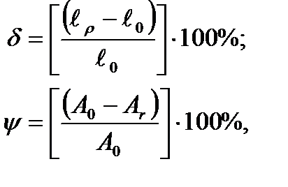
where  is the original specimen length;
  – is the specimen length after the rupture; А0 - is the original specimen cross-section; Аr is the minimum specimen cross section after the rupture.
The more is  and
and  , the more plastic the materials are. The materials having very small plasticity are called brittle. The tension diagram of the brittle materials does not have upper and lower yield points.
The steel compression diagram coincides with the tension diagram up to the yield point, the steel test results in tension and compression being the same.
The test results in tension and compression for cast – iron differ from each other considerably; the tensile strength is 3,5 times lesser than in compression. In other words, cast – iron works essentially worse in tension than in compression.
Notice, that only low carbon steel and some non-ferrous alloys have strongly marked upper and lower yield points.
The conventional yield strength term is introduced i.e. the stress under which the specimen unit residual elongation is equal to 0,2% for the plastic materials not having the tension diagram with sharply expressed upper and lower points (medium – carbon, high – carbon and alloy steels) or without them (copper, duralumin).
It should be mentioned that the materials division into ductile and brittle ones is but conventional, for depending on the character of the acting load the brittle material can acquire the plastic material properties while the ductile material acquires properties of the brittle material. Thus, under low temperatures or impact load for example, a detail made from a plastic material breaks without a local area increase line as a brittle detail.
Дата добавления: 2020-10-25; просмотров: 675;


