Stresses and a longitudinal deformation in tension and compression
The deformation type with only an axial force setting up at any bar cross section is called tension or compression. The beams with a straight axis (straight beams) in tension or compression are commonly named bars.
Let us consider the straight weightless bar rigidly clamped on the left and with the active force F and 2F acting along its axis (Fig.2.1).
The beam parts of the constant section limited by cross planes with by cross planes with active and reactive forces applied in them are called regions. The beam in Fig. 2.1 consists of two regions. Let us determine the normal forces N1 and N2 at the regions by applying the method of sections. We cut the beam at the first region by the cross section 1-1. The internal distributed forces will act at all points of the beam whose resultant force will be determined from the equilibrium condition of one of the beam parts (for example, the right one from the section):
 thus
thus 
| 1 F 2 |
| 2F |
| 2F |
| F |
| { |
| N1 |
| 1-st region |
| 2-nd region |
Fig. 2.1.
For the equilibrium of the remaining portion of the bar at the section 1-1 only the force N1 directed along the axis i.e. the normal force, must be applied. The normal force at the section 2-2 of the second region will be N2 = 2F.
So, the normal force at the bar cross-section is equal to the algebraic sum of the external forces of one side of the section (all forces are thought to be directed along the bar axis).
It is evident that the normal force within the limits of one region will have a constant value. It should be kept in mind that while considering the equilibrium of the left end of the bar, we must input the clamped end reaction into the equation, the reaction being determined by considering the whole of the bar equlibrium.
We shall further consider the normal tension forces (directed away from the section) positive and the compressive ones (directed toward the section) will be considered negative.
While studying a number of deformations, we will think of the bars as consisting of a numerous number of filaments parallels to the axis and suppose that under tension and compression the filaments do not press on each other (this assumption is called the hypothesis of the filament absence of pressure).
If we manufacture a straight bar from rubber (for a greater visuality) then draw a longitudinal and tranverse linear grid on its surface, we can note the following:
1) the transverse lines remain in the planes perpendicular to the axis and the distances between them will increase;
2) the longitudinal lines remain straight and the distances between them will decrease.
This experiment makes it possible to draw a conclusion that the hypothesis of the plane section is correct, hence, the filaments are elongated by one and the same quantity.
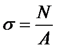
All the above said suggests that only normal stresses arise tension and compression distributed at the section. They can be calculated by the formula:
 ,
,
where N is the normal force, A is the cross section area.
It is evident that the section shape does not influence on the stresses under tension and compression.
The distribution law of stresses at the sections near the points of tension and the compressive forces applied will be more complicated, but we shall neglect it and admit that the stresses are distributed equally, the normal force and stress values are changed by jumps in the section with a concentrated force.
To vividly depict the normal force and normal stress distributions the plots are drawn, called the diagrams (epure), the same rule of signs being applied for normal forces.
Let us pass over to deformations. Imagine a straight bar of the constant cross section A and the length  ceamped at one end and loaded by the tensional force F at the other end. Under the action of this force the bar elongates over the Δ
  value which is called the absolute elongation.
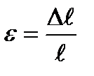
The relation of the absolute elongation Δ  to the original length
  is called the unit strain and denoted by e:
  .
.
2.2. Hooke,s law in tension and compression
The relation between the stress and the strain in tension and compression is called Hooke’s law, established by English physicist Robert Hooke in 1678.
Hooke’s law in tension and compression is correct only within definite limits of loading and is formulated as follows: normal stress is directly proportional to the unit strain or shortening.
Hooke’s law can be written matimacally:  .
.
The coefficient of proportionality E characterizes the material rigidity i.e. its capability to resist the elastic deformations in tension or compression and which is called the modulus of elasticity or the modulus of direct elasticity or Young,s modulus. Both the modulus of elasticity and the stresses are expressed in the same units the Pa – units.
The E values for some materials, MPa, are as follows
| Cast iron Steel Copper Alloy aluminum Tree (along fibre) Polymeric compound Capron | - (1,5 ¸ 1,6 ) .105 - (1,96 ¸ 2,16) .105 - (1,1 ¸ 1,3 ) .105 - (0,69 ¸ 0,71) .105 - (0,1 ¸ 0,16) .105 - (0,06 ¸ 0,1 ) .105 - (0,01 ¸ 0,02) .105 |
If we substitute the expressions 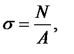
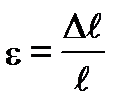 into the Hooke’s law formula we receive:
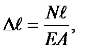
The product ЕА in the denominator is called the section rigidity under tension and compression; it characterizes physical and mechanical material properties and geometric dimensions of a bar cross section simultaneously.
The relation  is called the longitudinal rigidity in tension or compression.
The above given Hooke’s formulas are applied only to the bars manufactured of the same material and their regions with the constant cross section and under the action of the normal force being constant.
For the bar having several regions which differ in material, the cross section dimensions, the normal forces are equal to the algebraic sum of the elongations and shortenings:  .
.
Дата добавления: 2020-10-25; просмотров: 995;

