Detailed Drafting of Assembly Drawing
Detailed drafting is drawing of separate parts according to the drawing of an assembly unit.
It is recommended to begin the process of detailed drafting with drawings of basic parts of an article. The drawing of every part is done in the following order.
1. Read the assembly drawing thoroughly. Do not concentrate too long on one part, but pass on to the adjacent part and come back to first part, if necessary. Determine the minimum number of views required to adequately represent each part. Locate the sectional planes, if necessary.To choose main view. It must give a complete picture of a shape and sizes of part.
2. To set the location of sectional views, sections, auxiliary views and other representations on the drawing; thus unnecessarily to adhere to the same location, as on the drawing of general view.
3. To choose a scale for the representation of a part, according to State Standard 2.302 - 68.
4. Separate small elements on a part are advisable to draw as detail sections.
5. To choose necessary format according to State Standard 2.301 - 68.
6. Use the following sequence for drawing:
– Draw the axes of symmetry and block in the overall dimensions of the views;
– Draw the main outlines;
– Make sectional views and sections, and cross-hatch them;
– Draw the dimension lines and arrow heads;
– Put in the dimension figures and check the dimensions of mating parts.
7. To put denotation of roughness of surfaces. One of the most important moments in the process of implementation of the detail drawing of a part is dimensioning and designation of roughness of its surfaces. Putting the denotations of roughness of surfaces of a part should be done according to State Standard 2.309 - 73.
7. Size numbers which are put on the drawing and which are characterized dimensions are determined by measurement of the representation of a part on the drawing of general view taking into account a scale. While putting size numbers the special attention should be taken to the sizes of surfaces which are joined. Arrangement of representations, location of size net, denotation of sizes, sections, roughness and other inscriptions, must be executed taking into account the rational use of the field of drawing.
8. Drawing of a part is completed by filling in the title block.
The example of the completed detail drawing is shown in fig.8.1
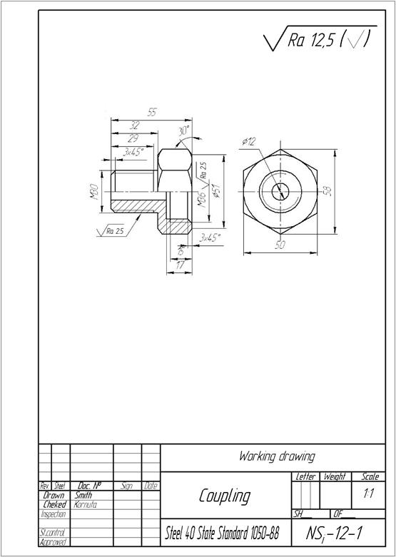
Fig. 8.1 – The example of the completed detail drawing
Дата добавления: 2016-07-18; просмотров: 2093;
Поиск по сайту
Узнать еще

Публикации по технике и механике
Публикации по биологии

Публикации по информатике

Публикации по строительству
Публикации по физике

Публикации по химии

Публикации по электронике

Публикации по искусству
Публикации по географии
Публикации по медицине