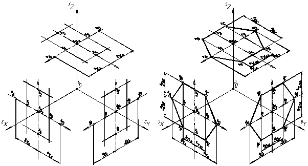
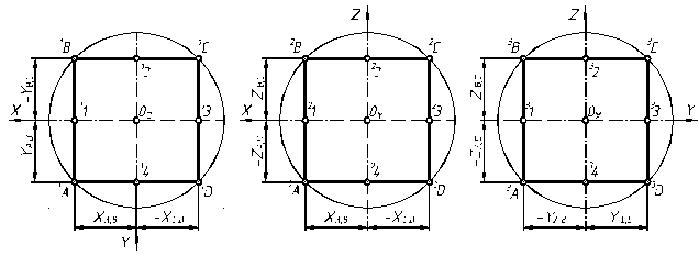
Figure 3.11 – The modeling of correct hexagon
Figure 3.11 shows a correct hexagon which is placed: a) parallel to the horizontal plane; b) – parallel to the frontal plane of projections; c) parallel to the profile plane of projections. The modeling of every point in a axonometrical projection generally is carried out after the description as shown in fig.3.8, we will use the well-known rule: the axonometrical projections of parallel lines are parallel between themselves. Through auxiliary points 1, 2, 3, 4, which are on axonometrical axes, draw lines parallel the proper axonometrical axes (see figure 3.12, a) and on their crossing mark the points of 0B, 0C, 0E, 0F. Points 0A, 0D are also on the proper axonometrical axes while connecting all of axonometrical projections of points, we’ll get an axonometrical projection of a figure (see fig. 3.12 b).
а) b)
Figure 3.12 – The modeling of correct hexagon
Axonometry of a free circle can be built as an aggregate of axonometrical projections of certain number of points of this circle. In any type of axonometry a circle will be projected in an ellipse. For the modeling of a rectangular іzometry of a circle (see fig. 3.13, a) which is in a coordinate plane (or in a level plane ), at first it is necessary to build axonometry of its center (points of 0X, 0Y, 0Z (figure 3.8)) to draw through the obtained point lines, parallel to the proper two axonometrical axes (segment: [1, 2] = D (there is a diameter of a circle inplane), and [3, 4] = D). Then draw the minor axis of an ellipse (segment [CD] = 0,71 ´ D (dash-dotted line)) parallel the axonometrical axis out of this plane, and a major axis (segment [AB] = 1,22 ´ D) which will be perpendicular (see figure 7.13, b). An ellipse is drawn on the obtained eight points by the curve (figure 3.13, c).

а) b) c)
Figure 3.13 – Axonometry of a free circle
Let’s consider the modeling of a rectangular dimetry of a plane figurewhich lies in a plane of projections (or in a plane level). Let’s remind, that it is a axonometrical projection with the identical indexes of distortion on two axes – X and Z.
А) b) c)
Дата добавления: 2016-07-18; просмотров: 1466;

