Modeling of rectangular іzometry of a cone.
For the direct cone (figure 3.19, a) axes of coordinates draw so that they coincided with the center of a circle in the basis, thus beginning of coordinates - 0 will be in the center of a circle. At first draw isometric axes for the modeling of a cone basis (figure 3.19, b). The basis of a cone is a circle, which is drawn in іzometry according to the description done before (figure 3.13). From a projection drawing we determine the location of a top – S (figure 3.19, c). Connect the top of a cone with the segments of formative tangential to the elliptic curve (figure 3.19, d).
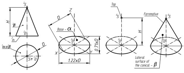
а) b) c) d)
Figure 3.19 –Modeling of rectangular іzometry of a cone
Modeling the rectangular іzometry of a cylinder.
For the direct cylinder (figure 3.20, a) axes of coordinates must coincide with the center of a circle in basis, thus beginning of coordinates - 0 will be in the center of a circle. At first draw isometrical axes for the modeling lower basis of a cylinder - b (figure 3.20, b). The basis of a cylinder is a circle which is drawn in іzometry according to the description done before (figure 3.13). From a projection drawing we determine the location of a cylinder upper base - a (figure 3.20, c). Connect upper and lower bases with the segments of formative of tangential to the elliptic curves (figure 3.20, d).
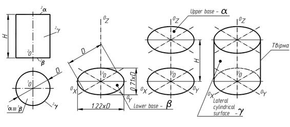
а) b) c) d)
Figure 3.20 – Modeling the rectangular іzometry of a cylinder
QuestionS for SELFcheck
1. Where are Axonometric projections used?
2. What types of axonometric projections do you know?
3. What are difference between dimetry and isometry?
JOINT
TYPES OF JOINT
Machines and mechanisms can be generally divided into component parts which form the unique functional system of the united elements and details.
Joints of details can be split-face and fixed.
Split-face joints allow to connect and disconnect details without a damage or plastic deformation of the both details.
Fixed joints are impossible to disconnect without a damage or plastic deformation of details of this connection (joints by welding, soldering, agglutination, press joints by riveting, etc.).
Split-face joints are divided into mobile in which the relative moving of connecting details (the key, splining but other) is possible, and immobile in which the connected details do not move in relation to each other (screw-thread joints by fixings, etc.). Let’s consider sectional screw-thread joints. Examining this question it is necessary to find out basic determinations and classification of screw-threads. Basic determinations of screw-threads are resulted in State Standard 11708-66.
Дата добавления: 2016-07-18; просмотров: 1659;
Поиск по сайту
Узнать еще

Публикации по технике и механике
Публикации по биологии

Публикации по информатике

Публикации по строительству
Публикации по физике

Публикации по химии

Публикации по электронике

Публикации по искусству

Публикации по географии
Публикации по медицине