BASIC CONCEPTS, DETERMINATIONS, CLASSIFICATION
Practical receptions of construction of visual images– axonometric projections and technical drawings are based on the theory of axonometric and perspective projections.
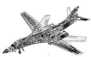
Visual images have a large practical value, they are widely used in different spheres of activity. A necessity in an visual image arises up at reading of drawing of an article, when it is difficult to imagine its structural form. A person who is not familiar with the methods of the ortogonal planning on three planes of projections, is hardly be able to imagine immediately what is shown in fig. 3.1.
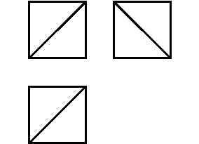
Figure 3.1 – Visual images
Axonometric projections are used to facilitate the process of spatial imagination. The example of this drawing is shown in figure 3.2. The view of a cube with a cut in a axonometric projection and its projection on three planes is shown.
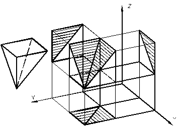
Figure 3.2 – Axonometric projections
Consequently, with the help of axonometric projections we can show the structure of the whole article and the structure of its separate parts, technological processes of treatment, assembling and installing. Axonometric projections are used for the transmission of the technical project of an author while planning and constructing new articles.
While looking at the visual depiction of an object, you get to know about it only on the basis of the unique appearance which is presented from one immobile point of view. Most of the component parts of an object, which find out its form on the whole might be seen on the visual depiction. Separate parts of an object must not fully close other its parts.
A view, got at parallel projections of an object together with the axes of rectangular co-ordinates of х, y, z to which it is taken in space, on some plane 0П is called an axonometric projection. . Thus the plane 0П, which an object is designed on, is called axonometric, and projections on it axes of 0х, 0у, 0z is called axonometric axes. The size of corner between them depends on the direction of planning and the position of a plane 0П according to the axes of х, y, z . The main positions of parallel projections are also used for axonometric projections : the axonometric projections of parallel lines are parallel between themselves; even segments which belong to the parallel lines are designed in even segments; if a point divides a segment in a certain correlation, its an axonometric projection divides the axonometric projection of cutting-off in that correlation. Segments on the axes of coordinates of х, y, z are designed generally with distortion. The sizes of projected objects are also distorted. The coefficients (indexes) of the distortion on axes equal the attitude of axonometric co-ordinates (on a drawing) toward natural (on an object). Depending on the direction of projected rays axonometric projections are divided into rectangular and oblique-angled. Axonometric projections are called rectangular, if a corner between projected rays and a plane of 0П is equal 90. °Axonometric projections are called oblique-angled, if a corner between projected rays and plane of 0П less than from a direct corner. Depending on the distortion of linear sizes of an object along axes axonometric projections are divided into isometry and dimetry. State standard 2.317-69 recommends to use two types of rectangular axonometric projections – isometry (figure 3.3) and dimetry (figure 3.4) and three types of oblique-angled axonometric projections – frontal isometry (figure 3.5), horizontal isometry (figure 3.6) and frontal dimetry (figure 3.7).
Дата добавления: 2016-07-18; просмотров: 2091;

