SOME GEOMETRICAL CONSTRUCTIONS
The Slope State Standard 8908 – 81
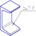
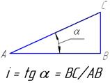
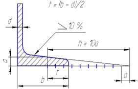
The slope characterizes inclination of one line or a plane according to the other (fig.1.21)
 |
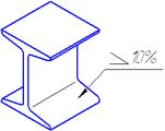
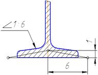
To mark the slope on a drawing a sign  or
or  is put before a size number, where Н is a font size. Slope examples are shown on figure 1.22.
|
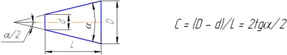
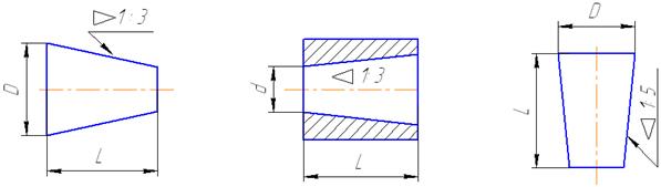
The Taper State Standard 8593-81
A taper is defined as unit alteration in a specified length measured along the axis in case of a shaft and a base line or a center line in case of flat pieces as shown in Fig. 1.23.
The taper is the correlation of difference of diameters of two cone cross-sections toward distance between them (fig.1.23).
|
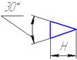
 To mark the taper on a drawing a sign
  or
or  is used which is put before a dimension (fig.1.24).
|
QuestionS for SELFcheck
1. What are basic formats according to the State Standard?
2. What kind of scales do you know?
3. When are linear and angular sizes used?
4. What types dimensioning on a drawing do you know?
5. How are slope and taper marked?
PROJECTION DRAWING
An important part of drawing work is the representation of the exact shaрe and size of a solid object. The solid which has length, breadth and thickness (three dimensional) is regarded as two dimensional on the surface of a drawing sheet.
State Standard 2.305-68 sets the rules of object depictions (wares, buildings and their component parts) on the drawings of all branches of industry.
The number of depictions of an object must be minimum but sufficient for determination of its form and forms all its elements.
The method of rectangular projection is used for the depictions, when an object is placed between the eye of the observer and the plane of projections. The basic planes of projections are chosen six verges of hollow cube, in the middle of which an object is placed which is projected on the internal verges of the cube. Then the basic planes of projections are combined with a frontal plane which result in a complex picture (fig.2.1).
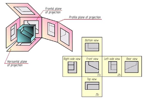
Figure 2.1– The basic planes of projections
A depiction on the frontal plane of projections is considered to be the main. An object is placed in relation to the frontal plane of projections so that a representation on it (the main depiction) gives the most complete picture of form and sizes of an object.
The depictions are divided into views, sectional views and sections according to a State Standard 2.305-68 standard .
VIEWS
A view is the depiction of a visible part of a surface of any object, facing the observer.
Views on the basic planes of projections are the main ones. They have the followings names (fig.2.1):
1 – front view (main view);
2 – top view;
3 – left-side view;
4 – right-side view;
5 – bottom view;
6 – rear view.
If all the views are placed on one sheet in direct projected connection, they are not inscribed.
If projected connection is broken, or views are separated by other depictions, or made on different sheets, then the view is accompanied by the capital letter of the Ukrainian alphabet, and the direction of planning is shown by a pointer with the same capital letter (fig.2.2).
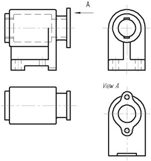
Figure 2.2 – Views of models
Besides basic, auxiliary and partial views are distinguished.
The auxiliary view is a view, which is received by projection on the plane, not parallel to any of basic planes of projections. This view is used, when a part of the object is inclined to the basic planes of projections and is represented on them in a distorted view. The auxiliary plane is placed parallell to the inclined element of the part and projected on this plane, without distortion. The auxiliary view is marked by a pointer and a letter. If the auxiliary view is placed in а direct connection with the corresponding image, the pointer and the inscription above the view are not inscribed (fig.2.3). The auxiliary view can be turned. Then a sign is added to its inscription .
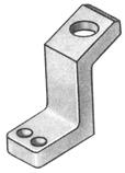
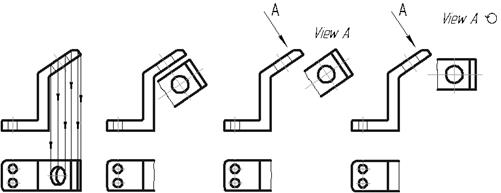
Figure 2.3 – The auxiliary views
The partial view is the view of the limited part of an object or its separate element (fig.2.4).
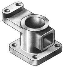
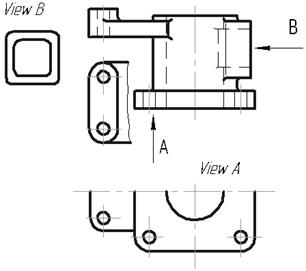
Figure 2.4 – The partial views
Partial views are made to show the form and sizes of a small element of the part, for example, a hole, a flange, ets. The partial view is made by projecting of the necessary element on one of the basic planes of projections. Partial views are placed on the field of drawing, without projectied connection with a basic image, but they are have to be nearer to the place of location and correspond to the position of element on the basic image. The partial view is limited on a drawing by a continuous wavy line or by lines of the contour of element. Partial views are marked in figure in the same way as the auxiliary ones.
Sectional VIEWS
A drawing must give the complete picture of external and internal form of a part. As it is generally known, the internal form of an object can be shown by hatched lines. However when the form of an object is complicated, there are a lot of hatched lines, which, crossing each other, darken the drawing and make it difficult to read. Sectional views is used to expose the internal form of an object.
A sectional views is a depiction of an object, relatively cut by one or several planes (fig.2.5). The sectional views shows what is placed in a cut plane and behind it. The internal contours of a part on a sectional views are shown by continuous main lines, as well as the visible contour of an object. What gets in a cut plane, is called a sectional view and it is shaded. Places, where a cut plane passes through cavities, are not shaded.
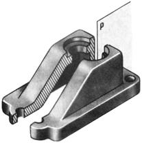
Figure 2.5 – A sectional views
Thus, to get a sectional drawing, it is necessary:
· To make a cutting plane in the right place;
· To set aside the part of an object, placed between the observer and the cutting plane;
· To project the remaining, part on the proper plane of projections and depict on the place of one of the basic views or on the free field of the drawing;
· To design a sectional drawing, if it is necessary, with inscript.
It should be remembered that a sectional viewsis a conventional representation and the part of an object, placed between an observer and a cutting plane, is set aside too. A conventional cutting touches only this depiction and does not influence all the others. So, for example, a sectional views on the frontal plane of projections does not change a top view.
Classification of sectional views.
The sectional views are divided according to the followings features:
1. Accoding to the position of a cutting plane in relation to the horizontal plane of projections sectional views are divided into horizontal, vertical and inclined.
The horizontal drawing is a sectional views which is formed by a cutting plane, parallel to the horizontal plane of projections. Most frequently this sectional views is disposed in the place of top or bottom views (fig.2.6).
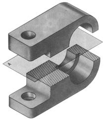
Figure 2.6 – The horizontal sectional view
The vertical drawing is a sectional drawing, which is formed by a cutting plane, perpendicular to the horizontal plane of projections. If a cutting plane is parallel to the frontal plane of projections, a vertical sectional views is named frontal; if it is parallel to the profile plane of projections, a sectional views is named a profile. As a rule, these sectional views are disposed in place of basic views: frontal in place of front view (fig.2.7,a), profile– in place of left-side view(fig.2.7,b).
a b
Figure 2.7 – The vertical sectional views
Sloping drawing is a sectional views which is formed by a cutting plane, which forms with the horizontal plane of projections a corner which differs from direct. These sectional views are used when an object has the inclined located elements (fig. 2.8). A sloping sectional views is designed on an auxiliary plane, parallel cutting, which is then combined with the plane of figure. It can be disposed at any place of the sheet both in direct projected connection and without it.
Figure 2.8 – The sloping sectional view
2. Depending on the position of cutting plane in relation to the basic measurings of object, sectional views can be divide into longitudinal and cross-sectional.
A cut is named longitudinal, if a cutting plane is directed along length or height of an object, and cross-sectional, if a cutting plane is directed perpendicularly to length or height of an object.
3. Depending on the amount of cutting planes, a sectional views can be divided into simple and complicated.
The simple drawing is a sectional views which formed by one cutting plane. All the above sectional views are considered to be simple.
The complicated drawing is a sectional views which is formed by two or more cutting planes. Such sectional views are divided into a offset section and broken.
An offset section is a complicated sectional views which is formed by parallel cutting planes (fig.2.9). A sectional views is done, as though depictions which are contained on all of parallel planes are combined in one plane (without denotation of limits of each planes).
Figure 2.9 – An offset section
The broken section is a complicated sectional views which is formed by unparallel cutting planes, thus one plane or some of them usually inclined to the basic planes of projections (fig.2.10). The broken sectional views is represented, as though a ramp is turned in vertical or horizontal position to combination with direction of basic cutting plane. When the combined planes appear parallel to one of basic planes of projections, it is necessary to dispose the broken sectional views in place of the proper view.
Figure 2.10 – The broken section
4. Depending on plenitude of implementation sectional views are divided into complete and partial sectional views.
A complete sectional views is a depiction which exposes the internal structure of an object on all of section, that when a cutting plane cuts an object through.
A partial sectional view is name a depiction which exposes the internal structure of a part only in the limited, separate place. Partial sectional views are separated from the whole part by a continuous wavy line which must not coincide with the lines of contour (fig.2.11).
Figure 2.11 – A partial sectional view
Denotation of sectional views .
Denotation of sectional views containe three elements (fig.2.12):
1. Position of cutting plane is specified the broken a secret line of a section. The initial and eventual strokes of a line of section must not cross the contour of the proper depiction.
2. On initial and eventual strokes it is needed to put pointers, indicative direction of look. Pointers must be inflicted in the distance 2...3 мм from the external end of stroke. At a complicated cut the strokes of the broken a secret line of a section conduct also at the bends of line of section.
Near pointers, indicative direction of look from exteriority of corner, formed a pointer and stroke of line of section, on a horizontal line inflict the uppercases of the Ukrainian alphabet. The letters should be in alphabetical order without reiterations.
3. A sectional views must be over the depiction according to the type «A — A» without underlining.
Figure 2.12 – Denotation of sectional views
If a cutting plane coincides with the symmetry plane of object, and a sectional views is executed in the place of the proper view in projected connection, for horizontal, vertical and profile sectional views , marking position of a cutting plane is not needed and a sectional views is not accompanied inscription. A frontal sectional views is not marked (fig. 2.13).
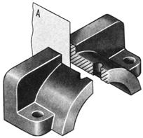
Figure 2.13 – Denotation of sectional views
However much simple sloping sectional views and complicated sectional views are always marked. Here are some examples of construction and denotation of sectional drawing. In a fig. 2.14 a horizontal sectional views is executed «A — A» in the place of view from above. A plane figure, lying in a cutting plane, is a figure of a section is shaded, and visible surfaces, located under a cutting plane, limited contour lines and are not shaded.
Figure 2.14 – A horizontal sectional view
A sloping sectional views is executed in fig. 2.15. It can be drawn in to projected connection in accordance with the direction, indicated pointers, or to dispose in any place of drawing. A local sectional views is executed, showing the through cylindrical openings on the basis of part on a main view.
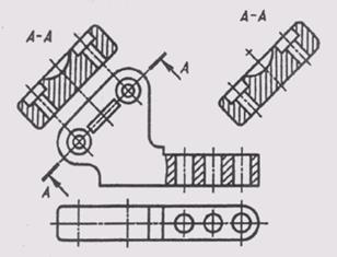
Figure 2.15 – A sloping sectional view
A complicated frontal sectional view is drawn in fig. 2.16 in a place of the main view, executed three frontal parallel planes. At the implementation of step sectional views all of parallel cutting planes are relatively combined in one, I.e. a difficult sectional views is designed as an simple. A transition from one cutting plane to other is not reflected on a difficult sectional drawing.
Figure 2.16 – A complicated frontal step sectional view
At the construction of the broken sectional views (fig. 2.17) one cutting plane is disposed parallell to some basic plane of projections, and the second cutting plane is turned to combination with first. The figure of section and sectional views located in it turn together with a cutting plane and is executed in the turned position by the figures of section.
Figure 2.17 – The broken sectional view
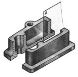
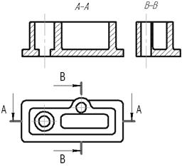
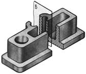
A part of the view and a part of the sectional views can be joined in one depiction of an object, dividing them with a wavy line (fig.2.18).
Figure 2.18 – A part of the view and a part of the sectional view
If we combine the half of view and half of sectional drawing, each of which is a figure symmetric, the ax of symmetry serves as a dividing them line. In fig. 2.19 four depictions of part are executed, thus on each of them the half of view is connected with the half of the proper sectional views . On a main view and left-side view a sectional views is disposed on the right of vertical ax by symmetries, and on top view and bottom view— on the right of vertical or from below from the horizontal ax of symmetry.
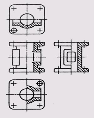
Figure 2.19 – Combining the half of view and half of sectional drawing
If the contour line of object coincides with the ax of symmetry (fig. 2.20), a border between a view and sectional views is specified a wavy line which is conducted so that to save the depiction of a rib.
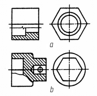
Figure 2.20 – Combining the half of view and half of sectional drawing
Shading of section figure, included in a sectional drawing, must be executed according to State Standard 2.306—68. Metals and their alloys designate in a section shading continuous striolas in thick from S/3 to S/2, which conduct parallell between itself under the corner of 45° to the lines of scope of drawing (fig. 2.21). The line of shading can bring slope to the left or to the right, but in a the same side on all of depictions of the same part.
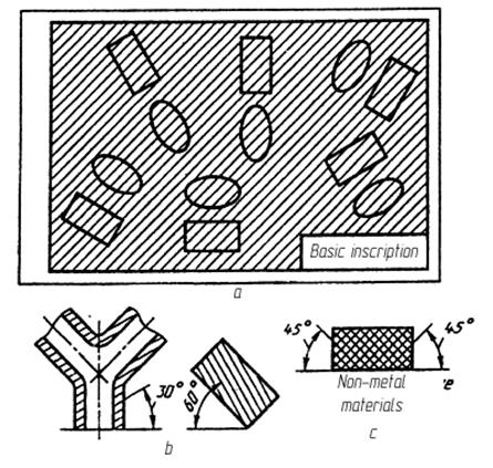
Figure 2.21 – Shading of section figure
Sections
Except of views and sectional views, sections are often used on drawings. A section is the depiction in a figure, got at a mental section one or a few planes, on in case when on a drawing only that got in a cutting plane. A section differs from a sectional views that on its represent that directly gets in a cutting plane only. Sections enter in the complement of sectional drawing, but can exist and as independent depictions.
Sections, which are not in sectional views, divide into taken away (carried out separately from a basic image, fig.2.22, a) and imposed (placed on the image of object, fig.2.22, b).
a b
Figure 2.22 – Types of sections
It is necessary to give a preference sections taken away, which can be disposed in a sectional views between parts of the same depiction.
The contour of the taken away section is drawn continuous by mainlines, and imposed — continuous thin, thus the contour of basic depiction is not interrupted in the place of location of the imposed section .
Denotation of sections in general case likes denotation of sectional drawings, I.e. the position of a cutting plane is represented by lines sections, on which inflict pointers, givings direction of look and designated the identical uppercases of the Ukrainian alphabet. Inscription on a type «A — A» (fig. 2.23) execute above a section in this case.
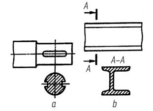
Figure 2.23 – Denotation of sections
For the asymmetrical imposed sections or executed in the break of basic image, section with pointers a line is drawn, but it is not designated in a letter (fig. 2.24). Imposed symmetric section andsymmetric section, executed in the break of basic image design without causing the line of section (fig.2.25).
Figure 2.24 – Denotation of sections
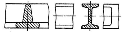
Figure 2.25 – Denotation of sections
If a cutting plane passes through the ax of surface of rotation, limiting opening or deepening, the contour of opening or deepening is drawn fully.
If a cutting plane passes through the through unround opening and section turns out consisting of separate independent parts, it is necessary to use sectional drawings, but not sections.
Дата добавления: 2016-07-18; просмотров: 2443;
Поиск по сайту

Публикации по технике и механике
Публикации по биологии

Публикации по информатике

Публикации по строительству
Публикации по физике

Публикации по химии

Публикации по электронике

Публикации по искусству
Публикации по географии
Публикации по медицине