A machining center is a highly automated machine tool capable of performing multiple machining operations under CNC in one setup with minimal human attention. Typical operations performed on a machining center are milling and drilling, which use rotating cutting tools.
The typical features that distinguish a machining center from conventional machine tools and make it so productive include:
1. Multiple operations in one setup;
2. Automatic tool changing;
3. Pallet shuttles;
4. Automatic workpart positioning.
Machining centers are classified as horizontal, vertical, or universal.
A modern CNC turning center, is capable of performing various turning and related operations, contour turning, and automatic tool indexing, all under computer control.
In addition, the most sophisticated turning centers can accomplish (1) workpart gaging (checking key dimensions after machining), (2) tool monitoring (sensors to indicate when the tools are worn), (3) automatic tool changing when tools become worn, and even (4) automatic workpart changing at the completion of the work cycle.
Several other machining operations should be included in our survey: (1) shaping and planing, (2) broaching, and (3) sawing.
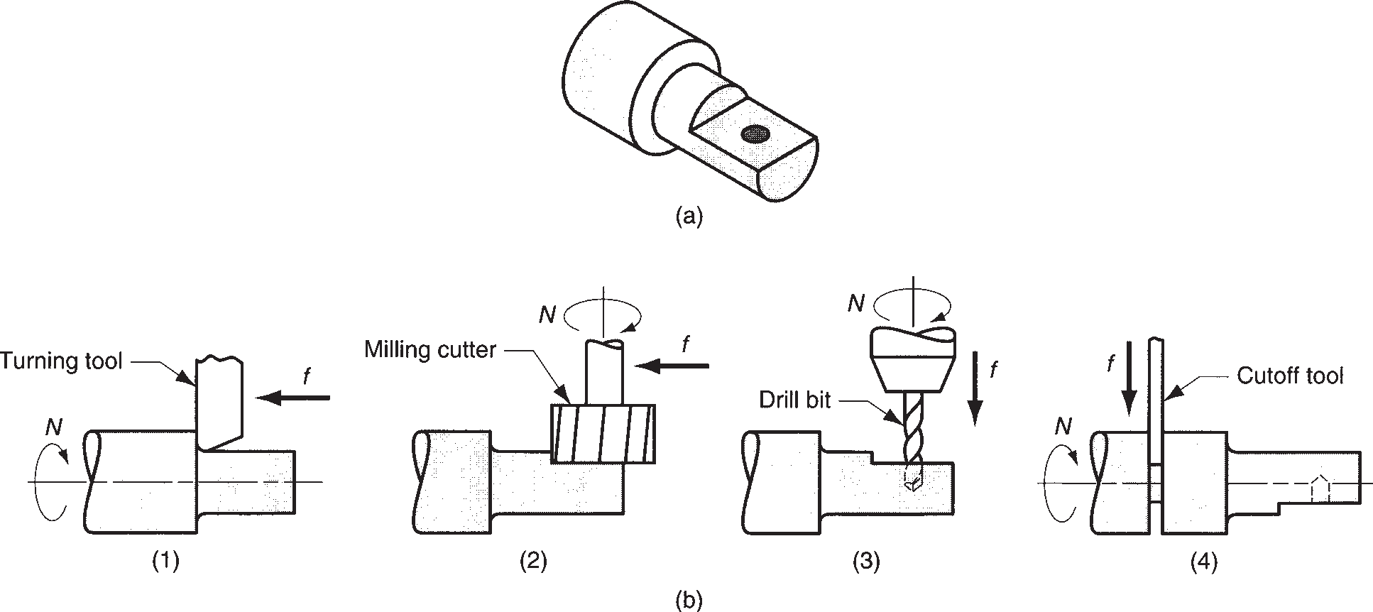
(a) example part with turned, milled, and drilled surfaces; and (b) sequence of operations on a mill-turn center: (1) turn second diameter, (2) mill flat with part in programmed angular position, (3) drill hole with part in same programmed position, and (4) cutoff.
Figure 8.1 – Operation of a mill-turn center:
Shaping and planing are similar operations, both involving the use of a single-point cutting tool moved linearly relative to the workpart. In conventional shaping and planing, a straight, flat surface is created by this action. The difference between the two operations is illustrated in Figure 8.2. In shaping, the speed motion is accomplished by moving the cutting tool; while in planing, the speed motion is accomplished by moving the workpart.
Figure 8.2 - (a) Shaping, and (b) planing
Shaping is performed on a machine tool called a shaper. The components of the shaper include a ram, which moves relative to a column to provide the cutting motion, and a worktable that holds the part and accomplishes the feed motion.
The machine tool for planing is a planer. Cutting speed is achieved by a reciprocating worktable that moves the part past the single-point cutting tool. Planers can be classified as open side planers or double-column planers. The open-side planer, also known as a single-column planer.
Broaching is performed using a multiple-teeth cutting tool by moving the tool linearly relative to the work in the direction of the tool axis, as in Figure 8.3. The machine tool is called a broaching machine, and the cutting tool is called a broach
Figure 8.3 – The broaching operation
Sawing is a process in which a narrow slit is cut into the work by a tool consisting of a series of narrowly spaced teeth. Sawing is normally used to separate a workpart into two pieces, or to cut off an unwanted portion of a part. These operations are often referred to as cutoff operations.
In most sawing operations, the work is held stationary and the saw blade is moved relative to it. According to the type of blade motion involved: (a) hacksawing, (b) bandsawing, and (c) circular sawing (Figure 8.4).
Figure 8.4 – Three types of sawing operations: (a) power hacksaw, (b) bandsaw (vertical), and (c) circular saw.