TEES (STATE STANDARD 8948-75)
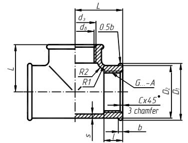
Figure 4.31 – Conventional drawings of a tee
Table 4.17
| Nominal bore, Dy, mm | Thread G, inch | L, mm | l , mm | D1, mm | D2, mm | b, mm | R1, mm | R2, mm | S, mm |
| 3/8 | 10.0 | 2.0 | 6.5 | 2.5 | |||||
| 1/2 | 12.0 | 28.6 | 26.6 | 2.0 | 2.7 | 5.5 | 2.8 | ||
| 3/4 | 13.5 | 34.9 | 32.4 | 2.5 | 3.3 | 6.3 | 3.0 | ||
| 15.0 | 42.1 | 39.6 | 2.5 | 3.2 | 6.5 | 3.3 | |||
| 17.0 | 3.0 | 3.4 | 3.6 | ||||||
| 19.0 | 3.0 | 4.0 | |||||||
| 21.0 | 70.5 | 3.5 | 2.5 | 4.5 |
The example of the conventional denotation of a tee with the nominal bore 20 mm: Tee 20 State Standard 8948-75.
The drawing of a joint is begun with the drawing of a pipe, then the view of connecting parts are drawn according to the sizes in tables (4.12 – 4.17). A pipe on the drawing is shown by not screw up in a connecting part on 2-4 mm (1-2 threads), that is why a thread on a pipe is at the face of the connecting part. Figure 4.32 shows the drawing of the pipe joint by a pipe coupling. An external thread on a pipe is drawn the same as on the bar of a bolt by a continuous contour line on the most diameter and by a continuous thin line on the internal diameter of a thread. Such view of a thread on a pipe will be in joint with other parts.
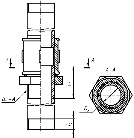
Figure 4.32 – Pipe joint by a pipe coupling
An internal thread in connecting parts remains unchanging only in the places not taken by the pipe.
PERMANENT JOINTS
As it was mentioned above, permanent joints are joints which are impossible to disconnect without the damage of connecting parts. Let’s consider such types of joints, as joints by welding, soldering, cementing.
WELDED JOINTS
Welding is a permanent method for making joints. Welding has replaced riveting in many industries because of saving in labour as well as material and reduction in weight by the use of lighter plates and the elimination of all overlaps and rivets. Standard steel shapes, plates and bars may be welded together to make machine frame, bases, jigs and fixtures, etc. For joining of very high pressure steam pipes, welding is the only acceptable process. The aircraft, automotive and ship building industries have developed welding as a major fabricating method for aluminium magnesium and steel.
Welding is defined as the localized, intimate union of metal parts in the plastic or plastic and molten state, with the application of blows or mechanical pressure or the union of parts in the molten state without any pressure. There are three main methods of welding, viz., forge welding, electric resistance welding and fusion welding, which may further be classified as shown in Fig. 4.33.
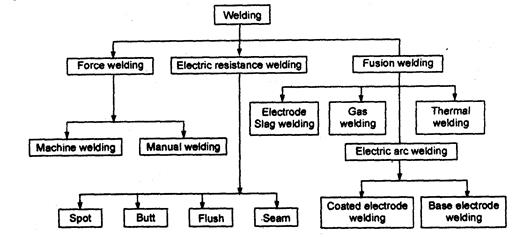
Figure 4.33 – Types of welding
The most common welding used in manufacturing of machinery is arc welding but gas welding is also used.
Arc welding is carried out with the help of a voltaic arc between an electrode and welded parts. The gas welding is conducted by flame of hot gas which is burned in the stream of oxygen.
At the resistance welding heating is carried out a heat which is selected at flowing of the powerful electric current through welded parts in the place of contact between them. The resistance welding is divided into butt and spot.
There are five basic form of welded joints, namely, edge, butt, lap, corner and tee. The various types of welded joints are shown in Fig. 4.34.

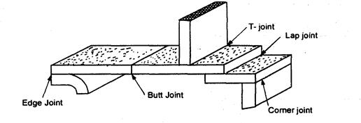
Figure 4.34 – Types of welded joints
1. Butt Joint-This type of Joint is used to join the ends of two plates, located in the same plane or 2 to 5 mm thick plates, the open square butt joint should be selected. But above 5 mm thickness, the joint with edge preparation on one or both sides may be recommended.
2. Lap Joint—It is used to join two overlapping plates such that the edge of each plate is welded to the surface of the other. This type of joint is suitable up to 3 mm thick plates.
3. Corner Joint-It is used to weld the edges of two plates this is suitable for both heavy and light gauges.This type of joint is commonly used in the construction of boxes, tanks, frames and other circular items.
4. Edge joint-The edge joint is used to join two parallel plates. This is generally used for sheet metal works.
5. T-Joint—T-Joint is used to join two plates, the surfaces of which are at right angle to each other. It is employed for thickness of plate’s up to 3 mm and is widely used in thin walled structures.
The weld is a part of the welded joint, formed in the place of a joint as a result of welding and which has structure, different from the structure of parent metal of the part.
The weldsare divided into types according to: duration, an external form, the form of edge preparation, the character of implementation.
Accordingto durationthe welds can be uninterruptedand interrupted. There are the uninterrupted– weld nonspaced on length (fig.4.35,а). Interruptedweldsare the welds with intervals on length (fig.4.35,b).
Interrupted welds can be chainand staggered.
Chainweld is one (fig.4.35,c) or bilateral interrupted weld of T-Joint in which intervals are place1d for both sides of the wall against each other (not represented).
Staggered weld is a double-sided interrupted weld of T-Joint in which intervals on one side of a wall are placed opposite the welded areas of its second side (fig.4.35, d).

а) b) c) d)
Figure 4.35 – Uninterruptedand interrupted welds
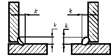
Some corner joints, T- joints and also lap joints are characterized by the size of leg K (fig.4.36).
A leg weld is the shortest distance from one surface of welding parts to the border of a corner weld and the surface of another weldable part.
a) b)
Figure 4.36 – A leg weld
 The form of edge preparation depends on the thickness of welding parts, the position of a weld in the space and other information. A bevel angle is an angle a between the bevel edges of weldable parts (fig.4.37).
Figure 4.37– A bevel angle
The way of making a weld depends on the thickness of weldable parts and technical conditions of welding. Welds are one-sided (fig.4.38, а) and two-sided(fig.4.38, b).

а) b)
Figure 4.38 – One-sided (a) and two-sided (b) welds
In the welds of the welded joints there are the obverse and reversesides. The obverseside of the weld is that from which welding is done (fig.4.39).
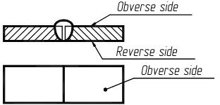
Figure 4.39 – Obverse and reverseweld sides
In accordance with State Standard 2.312-72 welds of the welded joints regardless of the method of welding are : visible – by a continuous mainline S thick (fig.4.40, b), invisible – by a stroke line s/2 thick (fig.4.40, a).

а) b)
Figure 4.40 - Welded joints
The visible single welded points regardless of the method of their welding are conventionally marked with the sign «+», which is drawn by continuous mainlines (fig.4.41). Invisible single points are not shown.
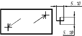
Figure 4.41 – The visible single welded points
To point the place of welds location of the welded joint utillize a line – foot-note with an one-sided pointer is used, which is drawn by a continuous thin line s/3...s/2 thick. The inclination of a line is foot-notes to the line of weld is recommended to draw under the angle of 30°-60°. To the line – foot-notes a horizontal point is joined of the same thickness where the complete description of welding is given.
Table 4.18 shows denotations of weld basic types of arc welding according to State Standard 5264-80.
Table 4.18
| The form of edge preparation | The way of making a weld | Form of weld section | Thickness of welding parts, mm | Conventional designation of the weld | Length of a leg weld, mm |
| Butt joint | |||||
| Weld without bevel edge | One-sided | 
| 1-6 | C2 | |
| Weld without bevel edge | Two-sided | 
| 2-6 | C4 | |
| Weld bevel one edge | Two-sided | 
| 4-26 | C5 | |
| Weld bevel two edge | One-sided | 
| 3-50 | C15 | |
| Corner Joint | |||||
| Weld without bevel edge | One-sided | 
| 1-6 | U2 | |
| Weld without bevel edge | Two-sided | 
| 2-6 | U3 | |
| Weld bevel one edge | One-sided | 
| 4-26 | U6 | |
| Weld bevel two edge | One-sided | 
| 12-60 | U9 | |
| T-Joint | |||||
| Weld without bevel edge | One-sided | 
| 2-30 | T1 | 3-8 |
| Weld without bevel edge | Two-sided | 
| 2-30 | T3 | 2-8 |
| Weld bevel one edge | One-sided | 
| 4-26 | T6 | |
| Lap Joint | |||||
| Weld without bevel edge | One-sided and interrupted | 
| 2-60 | H1 | |
| Weld without bevel edge | One-sided | 
| 2-60 | H2 |

a b
Figure 4.42 – The example of T-Joint (a) and interrupted lap welded joint(b)
The example of T-Joint T1 is shown in fig.4.42 (a). It is weld without bevel edge, two-sided, with length of a leg weld 5 mm.
The example of an interrupted lap welded joint H6 is shown in fig.4.42 (b). Width of a weld is 6 mm, length of a weld is 50 mm., pitch of a joint is 100 mm.
Дата добавления: 2016-07-18; просмотров: 2020;

