Washer 20.01.016 State Standard 11371-78.
Table 4.8
| Nominal thread diameter dn | d1 type | d2 | S | |
| 17.5 | 3.0 | |||
| 3.0 | ||||
| 3.0 | ||||
| 3.0 | ||||
| 4.0 |
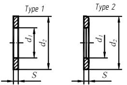
Figure 4.20 – Types of washers
THREAD JOINTS
Basic types of joints with the use of considered previously connecting elements are connection by a bolt, screw, stud, and also pipe joints. These types of joints (except of a pipe) have the three depictions: structural, simplified and conventional.
The structuraldepiction suits all structural elements of the parts of a joint.
The simplifieddepiction is used for details without chamfers, a thread is represented along the length of a bar of a thread part, a clearance between a bar and an opening is not shown.
A conventionaldepiction is used in those cases, when the diameter of a bar on a drawing less than 2 mm. State Standard 2.315:2008 is used for simplified joints.
Pipe joints are done only structurally.
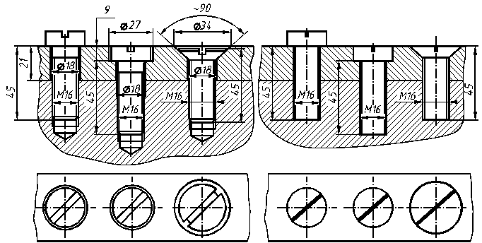
BOLT JOINTS
A bolt joint consists of a bolt – 3, a nut –5 and a washer –3 (fig.4.21, а). There are two parts in the bolt joint also (d1 and d2 – their thickness).
At the structural drawing of a thread connection opening diameter equals 1.1×dn (where dn is a nominal diameter of a bolt thread). Actual working length of a bolt is found as a sum of the followings parameters: L=d1+ d2 +Hn +Sw + 0.25×dn,
where d1 and d2 – the thickness of connecting parts, Hn– the thickness of a nut, Sw – the thickness of a washer, dn – the nominal diameter of a thread. The received sum is rounded to the nearest from the resulted standard row of workings lengths – L at table 4.9.
Table 4.9
| Working length of a bolt L, mm | Threaded length l0 according to the set nominal diameter of a thread dn | ||||
| 50,55,60,65,70,75,80 |
At the simplified drawing of a bolt joint for the calculation of working length of a bolt - L the dependence is used:
L=d1 + d2 +1,3×dn,
where d1 and d2 – the thickness of connecting parts, dn – the nominal diameter of a thread.
The parameter 1,3×dn approximately takes into account the structural sizes of the thickness of a washer, the height of a nut and stocked on length of a bolt. For the implementation of the simplified drawing of a bolt joint the followings correlations are used:
D=2´ dn; Dw=2,2´ dn; H=0,8´ dn; Sw=0,15 ´ dn; h=0,7´ dn.
The structural drawing of a bolt joint is presented in figure 4.21, a and it is simplified – in figure 4.21, b.
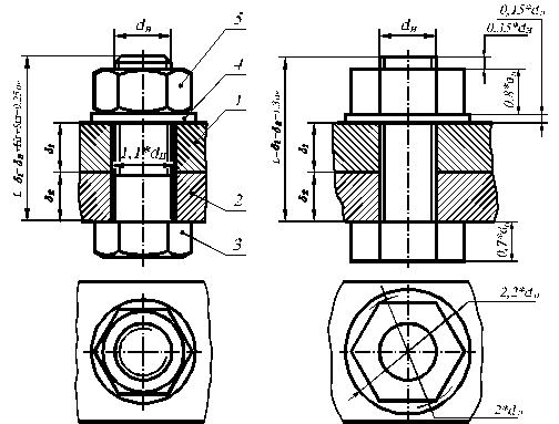
а) b)
Figure 4.21 – The bolt joint
STUD JOINTS
A stud joint consists of a stud - 3 (figure 4.22), a washer - 4 and a nut - 5. An opening is shown in a part 1, its diameter equals 1,1´ dn (where dn is a nominal diameter of a stud thread) at the structural drawing of a thread joint. Actual working length of a stud is found as a sum of the followings parameters:
L =d1+Hn +Sw + 0.25×dn,
where d1 is the thickness of a connecting part, Hnis the thickness of nut, Swis the thickness of a washer, dn is the nominal diameter of a thread. The received sum is rounded to the nearest from the resulted standard row of workings lengths - L at table 4.10.
Table 4.10
Threaded length l0 according to the set nominal thread diameter dn
| Working length of a stud L, mm | dn=16 | dn=18 | dn=20 | dn=22 | dn=24 |
| l0=L–0,5×dn | l0=L–0,5×dn | - | - | - | |
| l0=L–0,5×dn | l0=L–0,5×dn | l0=L–0,5×dn | - | - | |
| l0=L–0,5×dn | l0=L–0,5×dn | l0=L–0,5×dn | l0=L–0,5×dn | - | |
| l0=L–0,5×dn | l0=L–0,5×dn | l0=L–0,5×dn | l0=L–0,5×dn | ||
| l0=L–0,5×dn | l0=L–0,5×dn | l0=L–0,5×dn |
This table shows the actual value of working length L according to the threaded length l0.
At the simplified drawing of a stud joint for the calculation of the working length of a stud - L the dependence is used: L=d1+1,3×dn,
where d1 is the thickness of a connecting part, dn is a nominal thread diameter.
The parameter 1,3×dn approximately takes into account the structural sizes of the thickness of a washer, the height of a nut and stocked on length of a stud. For the implementation of the simplified drawing of a stud joint the followings correlations are used: D=2´ dn; Dw=2,2´ dn; H=0,8´ dn; Sw=0,15 ´ dn.
The structural drawing of a stud joint is shown in figure 4.22, and it is simplified in figure 4.22, b.
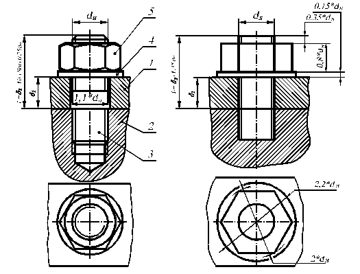
а) b)
Figure 4.22 – The stud joint
The parameters of a stud jack are found according to the followings dependences:
dopening=0,85´ dn; Lopening=L1+0,5´ dn.
According to these parameters a stud jack is done in figure 4.23.
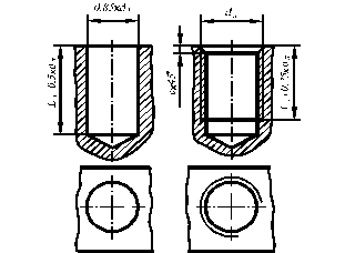
Figure 4.23 – The stud jack
SCREW JOINT
The thickness of an overhead joining part and parameters of a screw are input data for the drawing of a screw joint. At the structural drawing of a screw joint (fig. 4.24, а, b, c) it is necessary to draw all structural elements of parts. The sizes of a thread, length of a screw and sizes of a base surface under a head fill in. A slot under a screwdriver is disposed under the corner 45° at the view from the face head. On the simplified drawing of a screw joint (fig. 4.24, d, e, f) the sizes of a thread and a length of a screw are marked. A slot under a screwdriver is represented an incrassate contour line. The thread opening under a screw is drawn like an opening under a stud.
а) b) c) d) e) f)
Figure 4.24 – The screw joint
The parameters of a base surface under a head of screw are regulated by State Standard 12876:2008.
Дата добавления: 2016-07-18; просмотров: 1707;
Поиск по сайту
Узнать еще
- CURRENT STATE OF APPLIED RESEARCH ON SPANISH
- Dimensioning State Standard 2.307-68
- DISEASES OF THE PROSTATE
- Establishment of the Written Standard
- Growth of the Spoken Standard
- Late Middle English. Reestablishment of English as the Language of the State and Literature
- LOCK NUTS (STATE STANDARD 8961-75 )
- MATTER AND ITS STATES

Публикации по технике и механике
Публикации по биологии

Публикации по информатике

Публикации по строительству
Публикации по физике

Публикации по химии

Публикации по электронике

Публикации по искусству
Публикации по географии
Публикации по медицине