Поточные схемы мембранных установок
Под поточными схемами понимаются способы соединения мембранных аппаратов между собой для достижения производственных целей. Задача инженера в данном случае – собрать аппараты таким образом, чтобы оптимизировать систему, т.е. добиться минимальной стоимости конечного продукта.
Принципиально существуют, как упоминалось выше (см. гл.2), два способа проведения процессов мембранного разделения: “Cross-flow” and “dead-end”.
Industrial application of dead-end method is occurred rarely, especially in cartridge membranes. Такие элементы не предполагают (или очень редко) проведение регенерации материала, и после того, как мембрана выработала ресурс, заменяются на новый целиком. Примером служат домашние фильтры для доочистки водопроводной воды.
В случае с cross-flow filtration часть концентрата отводят из МЭ для увеличения рабочего ресурса. При этом также существует две конфигурации потоков – транзитная и циркуляционная. В транзитной схеме раствор проходит через мембранный аппарат, концентрируясь по длине. Наибольшее значение здесь имеет снижение линейной скорости потока.
В циркуляционной схеме скорость потока остается постоянной за счет возврата части концентрата с помощью циркуляционного насоса, установленного на обводной линии. Основным параметром контроля здесь является рост концентрации.
A ‘‘cross-flow’’ membrane is by definition one in which the ‘‘feed flow’’ between two membrane sheets passes through the element and leaves it as ‘‘concentrate-flow.’’ The cross-flow is diminished by the permeate flow along the axis of the membrane. Also, the cross-flow results in a shear along the membrane surface, which may erode some deposits.
Далее приведены формулы для расчета процессов в cross-flow filtration systems.
Основные формулы
Mass and flow balances equations
Flow balance
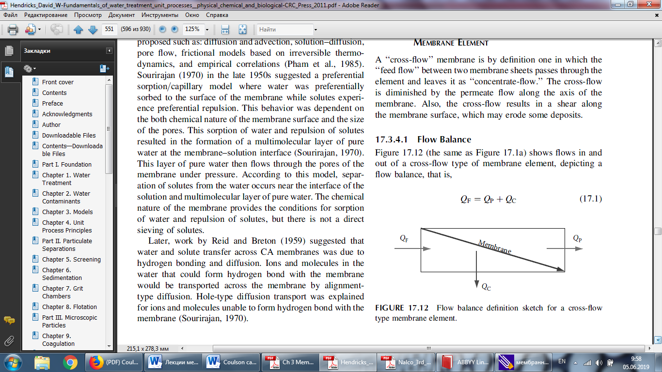
Figure XX. Flow balance definition sketch for Cross-flow membrane element
Figure XX shows flows in and out of a cross-flow type of membrane element, depicting a flow balance, that is,
where QF is the feed flow (m3/s)
QP is the permeate flow (m3/s)
QC is the concentrate flow (m3/s)
The flow balance is the basis for further definitions. The feed flow, QF, is the influent flow to a given membrane element after whatever pretreatment occurs. The permeate flow, QP, is what passes through the membrane, and the concentrate flow, QC, leaves the membrane pressure vessel (but not through the membrane).
4.1.2. Mass balance and pressures
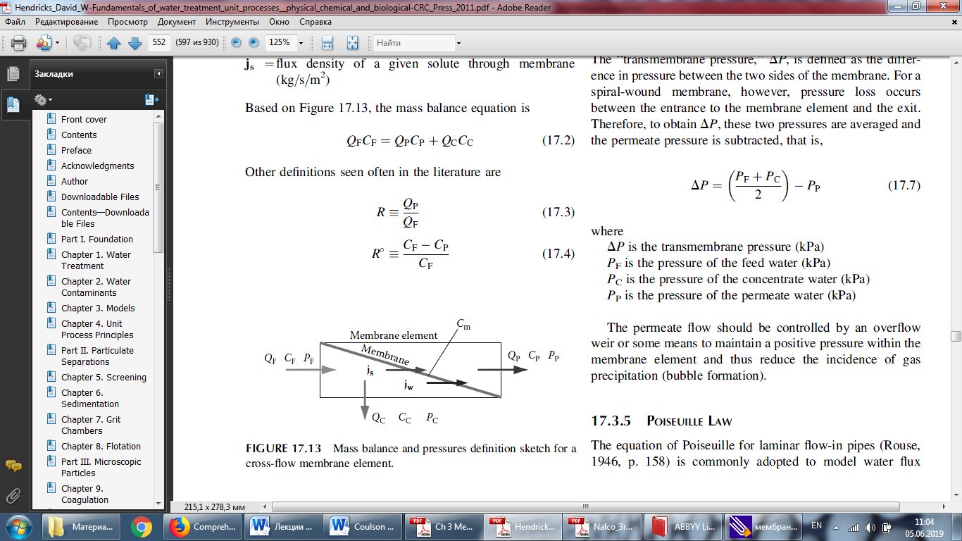
Figure XX. Mass balance and pressures definition sketch for a cross-flow membrane element.
Figure XX defines the flows, pressures, and solute concentrations for a cross-flow membrane element. The system is the same as depicted in Figure XX except that concentrations and pressures are shown also.
The terms in Figure XX are defined:
QF –flow of feed water (m3/s)
QC – flow of concentrate water (m3/s)
QP – flow of permeate water (m3/s)
CF – solute concentration in feed water (kg/m3)
CC – concentration of solute in concentrate water (kg/m3)
CP – concentration of solute in permeate water (kg/m3)
Cm– concentration of solute at the surface of membrane (kg/m3)
PF – pressure of feed water (N/m2)
PC – pressure of the concentrate water (kg/m2)
PP – pressure of the permeate water (kg/m2)
jw – flux density of water through membrane (m3/s·m2)
js – flux density of a given solute through membrane (kg/s·m2)
Based on Figure XX, the mass balance equation is
Other definitions seen often in the literature (and in chapter 2) are
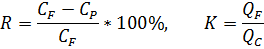
where R – selectivity
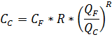
then concentrations CP and CC for real RO-modules can be founded:
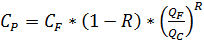 or
or 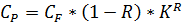
4.1.3. Water flux density
Water flux density through a membrane is defined:

where A – surface area of the membrane, m2;
JW = G – permeability of the membrane, m3/m2*h
4.1.4. Solute mass flux
Solute mass flux density is defined as the mass of a solute passing through a unit area of membrane per unit of time, that is,

where jS is the mass flux of solutes through the membrane (kg/s*m2)
A is the total area of membrane in filtering module (m2)
QP is the flow of the permeate water (m3/m2 *s)
CP is the solute concentration in the permeate water (kg/m3)
4.1.5. Transmembrane pressure
The ‘‘transmembrane pressure,’’ ΔP, is defined as the difference in pressure between the two sides of the membrane. For a spiral-wound membrane, however, pressure loss occurs between the entrance to the membrane element and the exit. Therefore, to obtain DP, these two pressures are averaged and the permeate pressure is subtracted, that is

where
ΔP is the transmembrane pressure (kPa)
PF is the pressure of the feed water (kPa)
PC is the pressure of the concentrate water (kPa)
PP is the pressure of the permeate water (kPa)
Дата добавления: 2020-04-12; просмотров: 765;
Поиск по сайту
Узнать еще
- А. Составление схемы технологического процесса
- Автоматизация работы конвейерных установок
- Автоматизированные поточные линии диффузии (АПЛ-Д)
- Автоматика газоиспользующих установок
- Алгоритм работы схемы
- Алгоритм режимов работы схемы пускателя ПВИ-250Б
- Алгоритм режимов работы схемы пускателя ПВИ-63Б, ПВИ-125Б
- Алгоритм режимов работы схемы пускового агрегата АПШ-1

Публикации по технике и механике
Публикации по биологии

Публикации по информатике

Публикации по строительству
Публикации по физике

Публикации по химии

Публикации по электронике

Публикации по искусству
Публикации по географии
Публикации по медицине