Position, contour and combined CNC system, CNC systems with a constant structure and system software implementation of algorithms
Introduction to CNC machining.
Numerically controlled (CNC) machine tool, robot, another object will be called the way of management on the basis of the prepared control program, the main indicators of which are given in digital form. Here, the managing software (Fig. 1.1) is a set of commands in the problems oriented programming language, which corresponds to a given algorithm operation of the machine, a robot, another object for the implementation of technology, transport and auxiliary operations. Under the CNC will understand the device outputs a control influence on the controlling devices of the object in accordance with the managing softwares, algorithms, processing and information on the state of the managed object.
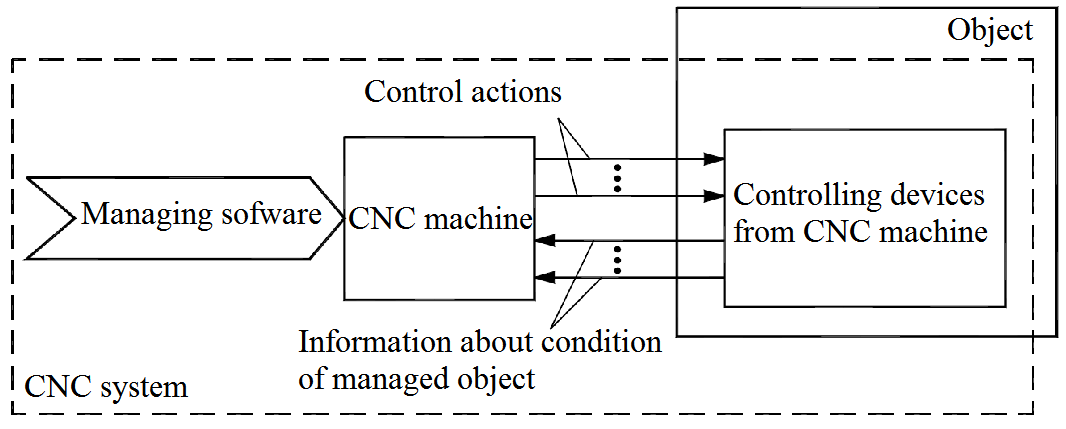
Figure 1.1 – Model of equipment management from CNC
To work with CNC machines it is necessary to know special rules of programming.
Figure 1.2 - The architecture of NC machine tools and machining operation flow
Machine control system, classification of machine control systems software, specifications and design features of the numerical control systems.
Point-to-Point NC
Point-to-point is also sometimes called a positioning system. In PTP the objective of the machine tool control system is to move the cutting tool to predefined location. The speed or path by which this movement is accomplished is not important in point-to-point NC. Once the tool reaches the desired location, the machining operation is performed at that position. NC drill presses are a good example of PTP systems. The spindle must first be positioned at a particular location in the workpiece. This is done under PTP control. Then the drilling of the holes is performed at that location, the tool is moved to the next hole location, and so forth. Since no cutting is performed between holes there is no need for controlling the relative motion of the tool and workpiece between hole locations. On positioning systems the speeds and feeds used by the machine tool are often used by the machine operator rather than by the NC tape. Positioning systems are the simplest machine tool control systems and therefore the least expensive of the three types. However processes such as drilling operations and spot welding. PTP is perfectly suited to task and any higher level of control is unnecessary.
Straight cut NC
Straight cut control systems are capable of moving the cutting tool parallel to one of the major axes at a controlled rate suitable for machining. It is therefore appropriate for performing milling operations to fabricate workpieces of rectangular configurations. With this type of NC systems, it is therefore appropriate for performing milling operations to fabricate workpieces of rectangular configurations. With this type of NC system, it is not possible to combine movements in more than single axis direction. Therefore, angular cuts on the workpiece would not be possible. An NC machine tool capable of performing straight cut movements is also capable of point-to-point movements.
Contouring NC
Contouring is the most complex flexible and the most expensive type of machine tool control. It is capable of performing both PTP and straight cut operations. In addition the distinguishing feature of the contouring NC system is their capacity for simultaneous control of more than one axis movement of machine tool Figures below illustrate the versatility of continuous path NC. Milling and Turning are the common examples of the use of contouring control.
Position, contour and combined CNC system, CNC systems with a constant structure and system software implementation of algorithms
Machining a certain geometry using a CNC machine tool passes through several stages before the actual machining takes place. The workflow of the machining process from the Computer Aided Design (CAD) system right through to the actual machining is typically characterized by the so called machining process chain. A general functional representation of such a chain is shown in Figure 2.1.
The machining process chain starts with the workpiece design using a CAD system. The data generated at this stage is a purely geometrical data describing the workpiece to be machined.
As a second step, the Computer Aided Manufacturing (CAM) system converts the geometric data into a tool path trajectory in the form of a machine understandable code called the part program. The control and drives unit, the brain of the CNC machine tool, analyzes the part program code and designs proper time optimal trajectories (position, velocity, acceleration and jerk trajectories) for the machine axes based on their capabilities and provides the machine’s actuators with the required driving signals in order to make sure that the geometry described by the part program is machined as fast as possible and with the requested contouring accuracy.
Figure 2.1 – Process chain from CAD/CAM-system to workpiece
In this thesis, the tool path trajectory will be assumed to be given in the form of a part program code, normally written in the form of G-Code. The focus will be mainly on the control and drives unit of the process chain. Figure 2.2 shows a typical structure of a control and drives unit of a single axis in a multi-axis CNC machine tool. The structure is, roughly, divided into three main parts: the NC kernel, the servo control and the mechanical system.
Figure 2.2 – Control structure of one axis in a CNC machine tool
Дата добавления: 2017-05-02; просмотров: 2176;
Поиск по сайту
Узнать еще
- BASIC TUNNELING SYSTEM
- CARDIOVASCULAR SYSTEM
- CARDIOVASCULAR SYSTEM SCHEME
- CHANGES IN THE NOMINAL SYSTEM IN MIDDLE ENGLISH AND NEW ENGLISH
- Changes in the vocabulary system in ME
- Changes in the vocabulary system in NE period
- Chapter III National Health Care System in Great Britain
- Digital Theatre System

Публикации по технике и механике
Публикации по биологии

Публикации по информатике

Публикации по строительству
Публикации по физике

Публикации по химии

Публикации по электронике

Публикации по искусству
Публикации по географии
Публикации по медицине