The Middle Ages and The Renaissance
After the fall of the Roman Empire, progress in European bridge building slowed considerably until the Renaissance. Fine bridges sporadically appeared, however. Medieval bridges are particularly noted for the ogival, or pointed arch. With the pointed arch the tendency to sag at the crown is less dangerous, and there is less horizontal thrust at the abutments. Medieval bridges served many purposes. Chapels and shops were commonly built on them, and many were fortified with towers and ramparts. Some featured a drawbridge, a medieval innovation. The most famous bridge of that age was Old London Bridge, begun in the late 12th century under the direction of a priest, Peter of Colechurch, and completed in 1209, four years after his death. London Bridge was designed to have 19 pointed arches, each with a 24-foot span and resting on piers 20 feet wide. There were obstructions encountered in building the cofferdams, however, so that the arch spans eventually varied from 15 to 34 feet. The uneven quality of construction resulted in a frequent need for repair, but the bridge held a large jumble of houses and shops and survived more than 600 years before being replaced. A more elegant bridge of the period was the Saint-Benezet Bridge at Avignon, Fr. Begun in 1177, part of it still stands today. Another medieval bridge of note is Monnow Bridge in Wales, which featured three separate ribs of stone under the arches. Rib construction reduced the quantity of material needed for the rest of the arch and lightened the load on the foundations.
During the Renaissance, the Italian architect Andrea Palladio took the principle of the truss, which previously had been used for roof supports, and designed several successful wooden bridges with spans up to 100 feet. Longer bridges, however, were still made of stone. Another Italian designer, Bartolommeo Ammannati, adapted the medieval ogival arch by concealing the angle at the crown and by starting the curves of the arches vertically in their springings from the piers. This elliptical shape of arch, in which the rise-to-span ratio was as low as 1:7, became known as basket-handled and has been adopted widely since. Ammannati's elegant Santa Trinita Bridge (1569) in Florence, with two elliptical arches, carried pedestrians and later automobiles until it was destroyed during World War II; it was afterward rebuilt with many of the original materials recovered from the riverbed. Yet another Italian, Antonio da Ponte, designed the Rialto Bridge (1591) in Venice, an ornate arch made of two segments with a span of 89 feet and a rise of 21 feet. Antonio overcame the problem of soft, wet soil by having 6,000 timber piles driven straight down under each of the two abutments, upon which the masonry was placed in such a way that the bed joints of the stones were perpendicular to the line of thrust of the arch. This innovation of angling stone or concrete to the line of thrust has been continued into the present.
The 18th and the 19th centuries
 By the middle of the 18th century, bridge building in masonry reached its zenith. Jean-Rodolphe Perronet, builder of some of the finest bridges of his day (Pont de Neuilly (1774), Pont Sainte-Maxence (1785), Pont de la Concorde (1791)), developed very flat arches supported on slender piers. In London the young Swiss engineer Charles Labelye evolved a novel and ingenious method of sinking the foundations, employing huge timber caissons that were filled with masonry after they had been floated into position for each pier. The 12 semicircular arches of Portland stone, rising in a graceful camber over the river, set a high standard of engineering and architectural achievement for the next generation and stood for a hundred years. Also in London, John Rennie built the first Waterloo Bridge with level-topped masonry arches.
In the 18th century, designs with timber, especially trusses, reached new span lengths. In 1755 a Swiss builder, Hans Grubenmann, used trusses to support a covered timber bridge with spans of 171 and 193 feet over the Rhine at Schaffhausen. One of the best long-span truss designs was developed by Theodore Burr, of Tonington, Conn., and based on a drawing by Palladio; a truss strengthened by an arch, it set a new pattern for covered bridges in the United States. Burr's McCall's Ferry Bridge (1815; on the Susquehanna River near Lancaster, Pa.) had a record-breaking span of 360 feet. Another successful design was the "lattice truss," patented by Ithiel Town in 1820, in which top and bottom chords were made of horizontal timbers connected by a network of diagonal planks.
Early trusses were built without precise knowledge of how the loads are carried by each part of the truss. The first engineer to analyze correctly the stresses in a truss was Squire Whipple, an American who published his theories in 1869. Understanding precisely how loads were carried led to a reduction in materials, which by then were shifting from wood and stone to iron and steel.
During the Industrial Revolution the timber and masonry tradition was eclipsed by the use of iron, which was stronger than stone and usually less costly. The first bridge built solely of iron spanned the River Severn near Coalbrookdale, Eng. Designed by Thomas Pritchard and built in 1779 by Abraham Darby. the Coalbrookdale Bridge, constructed of cast-iron pieces, is a ribbed arch whose nearly semicircular 100-foot span imitates stone construction by exploiting the strength of cast iron in compression. Iron bridges were judged to be technically the best of their time. The use of relatively economical wrought iron freed up the imaginations of designers, and one of the first results was Telford's use of chain suspension cables to carry loads by tension. His eyebar cables consisted of wrought-iron bars of 20 to 30 feet with holes at each end. Each eye matched the eye on another bar, and the two were linked by iron pins. The first of these major chain-suspension bridges and the finest of its day was Telford's bridge over the Menai Strait in northwestern Wales. At the time of its completion in 1826, its 580-foot span was the world's longest. In 1893 its timber deck was replaced with a steel deck, and in 1940 steel chains replaced the corroded wrought-iron ones. The bridge is still in service today.
The rise of the locomotive as a mode of transportation during the 19th century spurred the design of new bridges and bridge forms strong enough to handle both the increased weight and the dynamic loads of trains. The most significant of these early railway bridges was Robert Stephenson's Britannia Bridge, also over the Menai Straits. Completed in 1850, Stephenson's design was the first to employ the hollow box girder. The hollow box gave the deck the extra stiffness of a truss, but it was easier to build and required less engineering precision— at the cost, however, of extra material. The wrought-iron boxes through which the trains ran were originally to be carried by chain suspension cables, but, during the building, extensive theoretical work and testing indicated that the cables were not needed; thus the towers stand strangely useless.
 Among the most important railway bridges of the latter 19th century were those of Gustave Eiffel. Between 1867 and 1869 Eiffel constructed four viaducts of trussed-girder design along the rail line between Gannat and Commentry, west of Vichy in France. The most striking of these, at Rouzat, features wrought-iron towers that for the first time visibly reflect the need for lateral stiffness to counter the influence of horizontal wind loads. Lateral stiffness is achieved by curving the towers out at the base where they meet the masonry foundations ( Eiffel's famous Parisian tower of 1889).
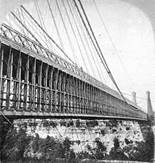
Niagara Bridge (USA), whose completion in 1855 vindicated John Roebling's conviction that the suspension bridge would work for railroads, lasted nearly half-a-century before it had to be replaced in 1896. At mid-century, it was the only form capable of uniting the 821ft (250m) gorge in a single span. This half-stereoscopic viewshows the massive stiffening trusses and the wire-cable stays that tied the deck superstructure to the walls of the gorge.
In 1855 Roebling completed an 821-foot-span railway bridge over the Niagara River in western New York state. Wind loads were not yet understood in any theoretical sense, but Roebling recognized the practical need to prevent vertical oscillations. He therefore added numerous wire stays, which extended like a giant spiderweb in various directions from the deck to the valley below and to the towers above. The Niagara Bridge confounded nearly all the engineering judgment of the day, which held that suspension bridges could not sustain railway traffic. The 1874 Eads Bridge was the first major bridge built entirely of steel, excluding the pier foundations. Designed by James Buchanan Eads, it has three arch spans, of which the two sides are each 502 feet and the middle is 520 feet. The Eads bridge was given added strength by its firm foundations, for which pneumatic caissons, instead of cofferdams, were used for the first time in the United States. Another innovation carried out by Eads, based on a proposal by Telford, was the construction of arches by the cantilevering method. The arches were held up by cables supported by temporary towers above the piers, all of which were removed when the arches became self-supporting.
BASIC FORMS
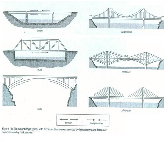
There are six basic bridge forms: the beam, the truss, the arch, the suspension, the cantilever, and the cable-stay. Figure 11 illustrates these forms and indicates the way loads are carried by showing the approximate location of compression (where material is squeezed together) and tension (where material is stretched).
Beam. The beam bridge is the most common bridge form. A beam carries vertical loads by bending. As the beam bridge bends, it undergoes horizontal compression on the top. At the same time, the bottom of the beam is subjected to horizontal tension. The supports carry the loads from the beam by compression vertically to the foundations.
When a bridge is made up of beams spanning between only two supports, it is called a simply supported beam bridge. If two or more beams are joined rigidly together over supports, the bridge becomes continuous.
Truss. A single-span truss bridge is like a simply supported beam because it carries vertical loads by bending. Bending leads to compression in the top chords (or horizontal members), tension in the bottom chords, and either tension or compression in the vertical and diagonal members, depending on their orientation. Trusses are popular because they use a relatively small amount of material to carry relatively large loads.
Arch. The arch bridge carries loads primarily by compression, which exerts on the foundation both vertical and horizontal forces. Arch foundations must therefore prevent both vertical settling and horizontal sliding. In spite of the more complicated foundation design, the structure itself normally requires less material than a beam bridge of the same span.
Suspension. A suspension bridge carries vertical loads through curved cables in tension. These loads are transferred both to the towers, which carry them by vertical compression to the ground, and to the anchorages, which must resist the inward and sometimes vertical pull of the cables. The suspension bridge can be viewed as an upside-down arch in tension with only the towers in compression. Because the deck is hung in the air, care must be taken to ensure that it does not move excessively under loading. The deck therefore must be either heavy or stiff or both.
Cantilever.A beam is said to be cantilevered when it projects outward, supported only at one end. A cantilever bridge is generally made with three spans, of which the outer spans are both anchored down at the shore and cantilever out over the channel to be crossed. The central span rests on the cantilevered arms extending from the outer spans; it carries vertical loads like in the supported beam or a truss -that is, by tension forces in the lower chords and compression in the upper chords. The cantilevers carry their loads by tension in the upper chords and compression in the lower ones. Inner towers carry those forces by compression to the foundation, and outer towers carry the forces by tension to the far foundations.
Cable-stay.Cable-stayed bridges carry the vertical main-span loads by nearly straight diagonal cables in tension. The towers transfer the cable forces to the foundations through vertical compression. The tensile forces in the cables also put the deck into horizontal compression.
TYPES OF BRIDGES
Introduction
Bridge designs differ in the way they support loads. These loads include the weight of the bridges themselves, the weight of the material used to build the bridges, and the weight and stresses of the vehicles crossing them. There are basically eight common bridge designs: beam, cantilever, arch, truss, suspension, cable stayed, movable, and floating bridges. The types of bridges vary in total length, the length of their spans, and the weight they can support. Before deciding which kind to build at a particular place, engineers determine the length of the structure and of each span. They also must consider the maximum load the bridge will carry and the materials available to construct the bridge.
Combination bridges may incorporate two or more of the above designs into a bridge. Each design differs in appearance, construction methods and materials used, and overall expense. Some designs are better for long spans. Beam bridges typically span the shortest distances, while suspension and cable-stayed bridges span the greatest distances.
Beam Bridges
Beam bridges represent the simplest of all bridge designs. A beam bridge consists of a rigid horizontal member called a beam that is supported at both ends, either by a natural land structure, such as the banks of a river, or by vertical posts called piers. Beam bridges are the most commonly used bridges in highway construction. Single-piece, rolled-steel beams can support spans of 15 to 30 m (50 to 100 ft). Heavier, reinforced beams and girders are used for longer spans.
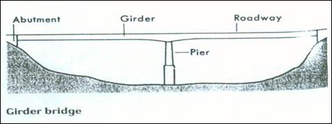
Girder Bridges
Girder bridges, which include many highway bridges, are made of beams called girders whose ends simply rest on piers or abutments. These bridges may be used to cross most areas. The span length of girder bridges ranges up to about 1.000 feet (300 meters).
There are two main types of girder bridges. In one type, called a box girder bridge, each girder looks like a long box that lies between the piers or abutments. The top surface of the bridge is the roadway. Box girder bridges are built of steel or concrete. In the other type of girder bridge, the end view of each girder looks like an I or a T. Two or more girders support the roadway. This type of bridge is called a plate girder bridge whenmade of steel, a reinforced or prestressed concrete girder bridge when made of concrete, and a wood girder bridge when made of wood.
TRUSS BRIDGES
Truss bridgesare supported by frameworks called trusses. The parts of the trusses are arranged in the form of triangles. Such bridges are built over canyons, rivers, and other areas. A truss bridge may have a main span that extends more than 1,000 feet (300 meters).
Each truss consists of steel or wood parts that are connected to form one or more triangles. The simplest truss consists of three parts fastened together at their ends to form a triangle.
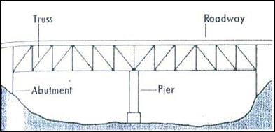
Most truss bridges have one set of trusses on each side of the roadway. The majority of modern truss bridges have the roadway on top of the trusses and are called deck truss bridges. The roadway of a through truss bridge runs between the trusses.
In a simple span truss bridge, each truss extends between two abutments or piers. In a continuous truss bridge, each truss has three or more such supports.
 Some locations are suitable for either a truss bridge or a girder bridge. In such cases, some engineers choose to build a truss bridge because it requires less construction material than the girder type. However, many engineers prefer a girder bridge because it is more attractive and easier to construct and maintain.
Arch bridges
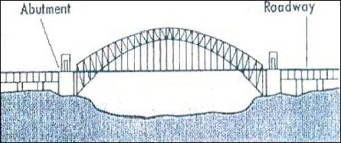
Arch bridges are structures in which each span forms an arch. The spans range up to about 1,700 feet (518 meters) long. The arch bridge is one of the oldest types of bridges. Early arch bridges consisted of large stone blocks wedged together to form an arch. Today, the majority of arch bridges that have short spans are made of concrete or wood. Arch bridges with long spans are built of concrete or steel.
Engineers must design arch bridges so that the sides of the arch do not spread apart and collapse the bridge. The roadway of some arch bridges lies on top of the arch and is supported by vertical columns called spandrel columns. These columns transfer the load of the roadway to the arch, which bears the weight of the bridge. The roadway of a tied arch bridge is below the curve of the arch. The roadway is supported by girders or other types of beams that hang from the arch. The girders or beams also connect to the ends of the arch to prevent the ends from spreading out. The abutments support the weight of the bridge.
Дата добавления: 2016-08-23; просмотров: 3652;
Поиск по сайту
Узнать еще
- Changes in alphabet and spelling in Middle and New English
- CHANGES IN THE NOMINAL SYSTEM IN MIDDLE ENGLISH AND NEW ENGLISH
- Decay of Noun Declensions in Early Middle English
- Dialects in Late Middle English. The London Dialect
- Early Middle English dialects
- Early Middle English Dialects. Extension of English Territory
- Early Middle English Written Records
- ENGLISH RENAISSANCE

Публикации по технике и механике
Публикации по биологии

Публикации по информатике

Публикации по строительству
Публикации по физике

Публикации по химии

Публикации по электронике

Публикации по искусству
Публикации по географии
Публикации по медицине