Electricity distribution
AC voltage can be stepped up or down by a transformer to a different voltage. High-voltage, direct current electric power transmission systems contrast with the mod common alternating-current systems as a means for the bulk transmission of еelectrical power. However, these tend to be more expensive and less efficient than transformers. Use of a higher voltage leads to more efficient transmission of power. The power losses in a conductor are a product of the square of the current and the resistance of the conductor, described by the formula P = I2R. This means that when transmitting a fixed power on a given wire, if the current is doubled, the power loss will be four times greater. Since the power transmitted is equal to the product of the current, the voltages also and the cosine of the phase difference cp (P = IVcosφ), the same amount of power can be transmitted with a lower current by increasing the voltage. Therefore it is advantageous when transmitting large amounts of power to distribute the power with extremely high voltages (sometimes as high as hundreds of kilovolts). However, high voltages also have disadvantages, the main ones being the increased danger to anyone who comes into contact with them, the extra insulation required, and generally increased in their safe handling. In the power plant the voltage is generated on three phase low voltage, with a frequency of either 50 or 60 hertz, and stepped up to a high voltage for distribution and stepped down, with a neutral, to a relatively low level for the com generally around 200 V to 500 V between phases and 100 V to 250 V between each phase and the neutral.
Three-phase electrical generation is very common and is a more efficient use of commercial generators. Electrical energy is generated by rotating a coil inside magnetic field, in large generators with a high capital cost. However, it is relatively simple and cost effective to include three separate coils in the generator stator (instead of one). These sets of coils are physically separated and at an angle of 120° to each other. Three current waveforms are produced that are 120° out of phase with each other, but of equal magnitude. Three-phase systems are designed so that they are balanced at the load; if a load is correctly balanced no current will flow in the neutral point. Also, even in the worst-case unbalanced (linear) load, the neutral current will not exceed the highest of the phase currents. For three-phase at low (normal mains) voltages a four-wire system like this is normally used, reducing the cable requirements by one third over using a separate neutral per phase. When stepping down three-phase, a transformer with a Delta primary and a Star secondary is often used so there is no need for a neutral on the supply
side. For smaller customers (just how small varies by country and age of install) only a single phase and the neutral or two phases and the neutral are taken to the property. For larger installs all three phases and the neutral are taken to the main board. From a three-phase main board both single and three-phase circuits may lead off (and in some cases also circuits with two phases (not to be confused with two-phase) and a neutral are led off). Three-wire single phase systems, with a single centre-tapped transformer giving two live conductors, is a common distribution scheme for residential and small commercial buildings in North America. A similar method is used for a different reason on construction sites in the UK. Small power tools and lighting are supposed to be supplied by a local center-tapped transformer with a voltage of 55 V between each power conductor and the earth. This significantly reduces the risk of electric shock in the event that one of the live conductors becomes exposed through an equipment fault whilst still allowing a reasonable voltage for running the tools.
A third wire is often connected between non-current carrying metal enclosures and earth ground. This conductor provides protection from electrical shock due to accidental contact of circuit conductors with the case of portable appliances and tools.
AC power supply frequencies
The frequency of the electrical system varies by country; most electric power is generated at either 50 or 60 Hz. Some countries have a mixture of 50 Hz| and 60 Hz supplies.
A low frequency eases the design of low speed electric motors, particularly for hoisting, crashing and rolling applications, and commutator-type traction motors for applications such as railways, but also causes a noticeable flicker in incandescent lighting and objectionable flicker of fluorescent lamps. 16.67 Hz power (1/3 of the mains frequency) is still used in some European rail systems, such as in Sweden and Switzerland.
Textile industry, marine, computer mainframe, aircraft, and spacecraft applications sometimes use 400 Hz, for benefits of reduced weight of apparatus or higher speeds.
AC-powered appliances can give off a characteristic hum at the multiples of the frequencies of AC power that they use. Most countries have chosen their television standard to approximate their mains supply frequency. This helps prevent power line hum and magnetic interference from causing visible beat frequencies in the displayed picture. Unless specified by the manufacturer to operate on either 50 or 60 Hz, appliances may not operate efficiently or even safely if used on other than the intended supply frequency.
The European Union (including the UK) has now officially harmonized on a supply of230 V 50 Hz. However they made the tolerance bands very wide at ±10%. Some countries actually specify stricter standards than this for example the UK specifies 230 V +10% -6%. Most supplies to the old standards therefore conform to the new one and do not need to be changed.
To be continued.
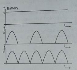
DIRECT CURRENT
Direct current (DC or "continuous current") is the constant flow of electric charge
from high to low potential. This is typically in a conductor such as a wire, but can also be through semiconductors, insulators, or even through a vacuum as in electron or ion beams. In direct current, the electric charges flow in the same direction, distinguishing it from alternating current (AC).
Дата добавления: 2017-10-04; просмотров: 2969;
Поиск по сайту

Публикации по технике и механике
Публикации по биологии

Публикации по информатике

Публикации по строительству
Публикации по физике

Публикации по химии

Публикации по электронике

Публикации по искусству
Публикации по географии
Публикации по медицине